Oil supply system for vehicle

a technology for oil supply systems and vehicles, which is applied in the direction of mechanical equipment, machines/engines, gearing details, etc., can solve the problems of deteriorating the rising characteristics of oil not reaching the inlet port of the hydraulic pressure produced by the mechanical oil pump b>202/b> does not exhibit appropriate rising characteristics

Inactive Publication Date: 2008-12-18
TOYOTA JIDOSHA KK +1
View PDF5 Cites 56 Cited by
  • Summary
  • Abstract
  • Description
  • Claims
  • Application Information

AI Technical Summary

Benefits of technology

[0009]The invention is made in light of the above-described circumstances. The invention provides an oil supply system for a vehicle, which includes a mechanical oil pump and an electric oil pump, and which makes it possible to avoid the situation in which air enters the mechanical oil pump while an engine is stopped and the rising characteristics of the hydraulic pressure produced by the mechanical oil pump during startup of the engine deteriorate due to presence of the air in the mechanical pump, and the situation in which the electric oil pump sucks the air and causes air-sucking noise.

Problems solved by technology

Therefore, for example, while the engine is stopped or while the vehicle is left unused for a long time, the oil leaks from the mechanical oil pump and the air enters the mechanical oil pump through a gap formed in the mechanical oil pump (for example, a gap between a case and a cover), which deteriorates the rising characteristics of the hydraulic pressure produced by the mechanical oil pump during startup of the engine.
However, the oil does not reach an inlet port of the mechanical oil pump 202 easily.
As a result, the hydraulic pressure produced by the mechanical oil pump 202 does not exhibit appropriate rising characteristics.
As a result, the fuel efficiency is reduced.
At this time, air-sucking noise may be caused.

Method used


Image

  • Oil supply system for vehicle
  • Oil supply system for vehicle
  • Oil supply system for vehicle

Examples


first embodiment

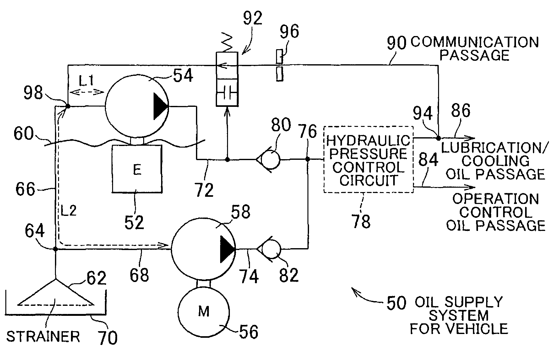
[0044]Hereafter, example embodiments of the invention will be described with reference to the accompanying drawings. FIG. 1 is a circuit diagram illustrating an oil supply system 50 for a vehicle according to the invention. The oil supply system 50 includes a mechanical oil pump 54 that is driven by an engine 52, which serves as a drive power source for a vehicle, and an electric oil pump 58 that is driven by an electric motor 56 when necessary. The oil supply system 50 is suitable for, for example, a hybrid vehicle that includes a hybrid vehicle drive unit 10 shown in FIG. 19, and an eco-run vehicle in which the operation of the engine 52 is stopped when the vehicle is stopped.

[0045]In the hybrid vehicle drive unit 10 in FIG. 19, torque from a first drive power generation source 12, which serves as a main drive power generation source, is transferred to an output shaft 14, which serves as an output member, and the torque is transferred from the output shaft 14 to paired right and l...

second embodiment

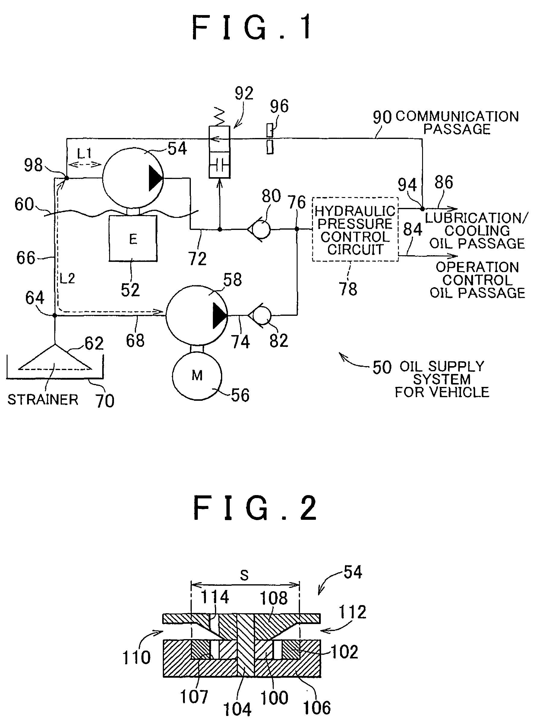
[0087]In addition, according to the invention, the communication passage 90 is connected to the connection portion close to the discharge port 112 of the mechanical oil pump 54. Therefore, even if the air remains in the mechanical oil pump 54 when the engine 52 is started because the engine-power cruise mode or the vehicle start / acceleration mode is selected, the air is promptly discharged to the communication passage 90 in accordance with the operation of the mechanical oil pump 54. Accordingly, the hydraulic pressure output from the mechanical oil pump 54 exhibits appropriate rising characteristics despite presence of the check valve 80. More specific description is provided below. Because the hydraulic pressure in the communication passage 90 is low, even if the hydraulic pressure output from the mechanical oil pump 54 is too low to open the check valve 80, the oil flows into the communication passage 90, and the air is discharged into the communication passage 90 together with t...

third embodiment

[0089]In the invention, a check valve 140, which permits an oil flow from the mechanical oil pump 54 toward the jet pump 128 but blocks an oil flow from the jet pump 128 toward the mechanical oil pump 54, is provided in the communication passage 90 as a blocking device instead of the pilot hydraulic pressure opening / closing valve 92. The pump-side port 98 of the communication passage 90 is connected to a connection portion of the oil intake passage 66 or of the mechanical oil pump 54, which is close to the inlet port 10, at a position above the oil level 60 of the oil in the transmission case.

[0090]In the oil supply system 124 for a vehicle, the jet pump 128 is provided in the bypass oil passage 126 that extends in parallel with the lubrication / cooling oil passage 86, and the oil is sucked into the jet pump 128 through the communication passage 90. Therefore, when the electric oil pump 58 is actuated in response to an operation for turning the power switch on, the oil and the air on...


PUM


Abstract

An oil supply system for a vehicle includes: a mechanical oil pump driven by an engine; an electric oil pump driven by an electric motor; a hydraulic pressure control circuit supplied with oil from the mechanical oil pump and the electric oil pump through an oil discharge passage for the mechanical oil pump and an oil discharge passage for the electric oil pump, which are connected to each other; a lubrication/cooling oil passage that is supplied with the oil from the hydraulic pressure control circuit; and a communication passage that provides communication between the lubrication/cooling oil passage and the mechanical oil pump. With this oil supply system, it is possible to prevent the electric oil pump from causing air-sucking noise, for example, in the motor-power cruise mode, and to improve the rising characteristics of the hydraulic pressure produced by the mechanical oil pump during startup of the engine.

Description

INCORPORATION BY REFERENCE[0001]The disclosure of Japanese Patent Application No. 2007-111623 filed on Apr. 20, 2007 including the specification, drawings and abstract is incorporated herein by reference in its entirety.BACKGROUND OF THE INVENTION[0002]1. Field of the Invention[0003]The invention relates generally to an oil supply system for a vehicle, which includes a mechanical oil pump that is driven by an engine and an electric oil pump that is driven by an electric motor, and, more specifically to a technology for improving the rising characteristics of the hydraulic pressure produced by the mechanical oil pump during startup of an engine.[0004]2. Description of the Related Art[0005]Japanese Patent Application Publication No. JP-2005-315271 (JP-A-2005-315271) describes an oil supply system for a vehicle, which includes a mechanical oil pump that is driven by an engine and an electric oil pump that is driven by an electric motor. In the oil supply system, an oil discharge passag...

Claims


Application Information

Patent Timeline
Patent Type & Authority Applications(United States)
IPC IPC(8): F16N13/00F16H57/02F16H57/027F16H57/04F16H61/00
CPCF16H57/04
Inventor KAKINAMI, TAKUMATABATA, ATSUSHIIWASE, YUJIATARASHI, TOMOOTESHIMA, ATSUSHI
Owner TOYOTA JIDOSHA KK
Why Eureka
Try Eureka