Height adjustable table
a technology of adjustable tables and adjustable legs, which is applied in the direction of adjustable height tables, kitchen equipment, stands/trestles, etc., can solve the problem of limiting the space available for users' knees
- Summary
- Abstract
- Description
- Claims
- Application Information
AI Technical Summary
Benefits of technology
Problems solved by technology
Method used
Image
Examples
second embodiment
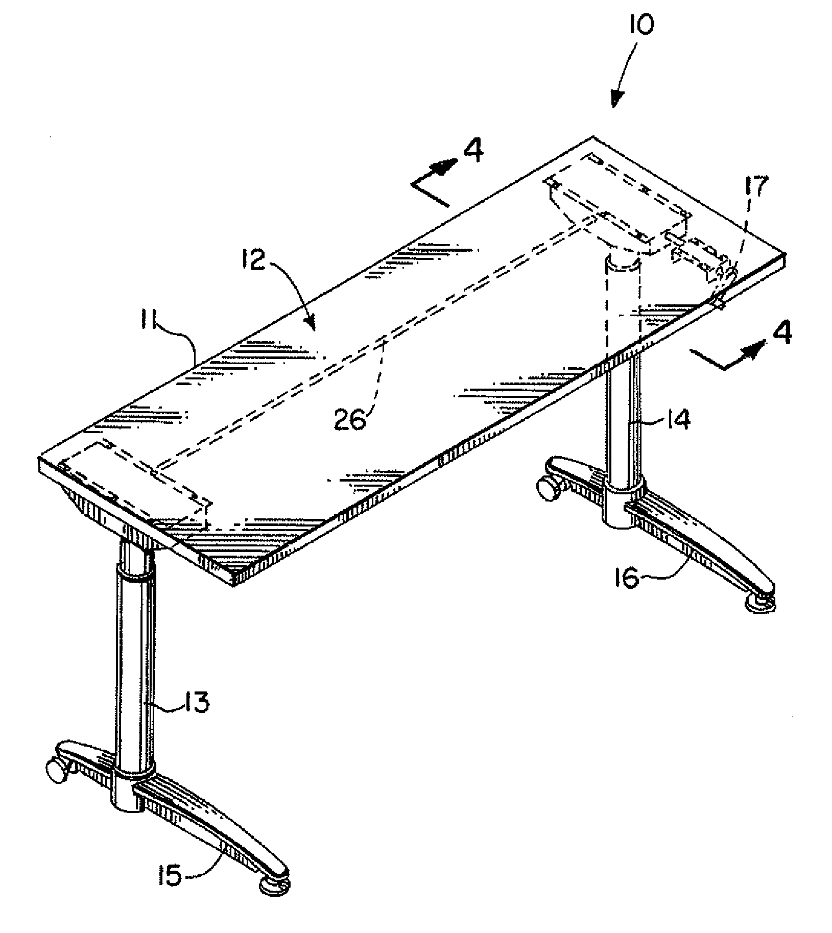
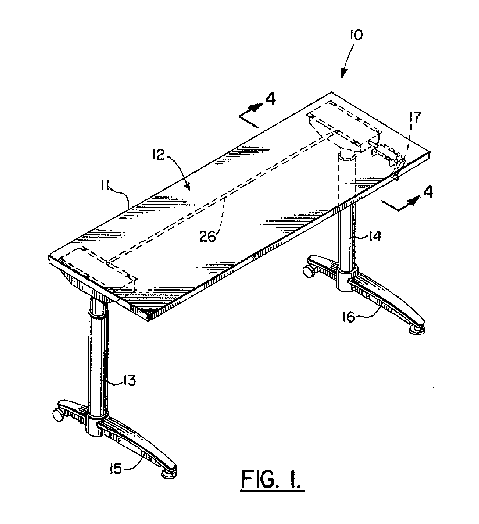
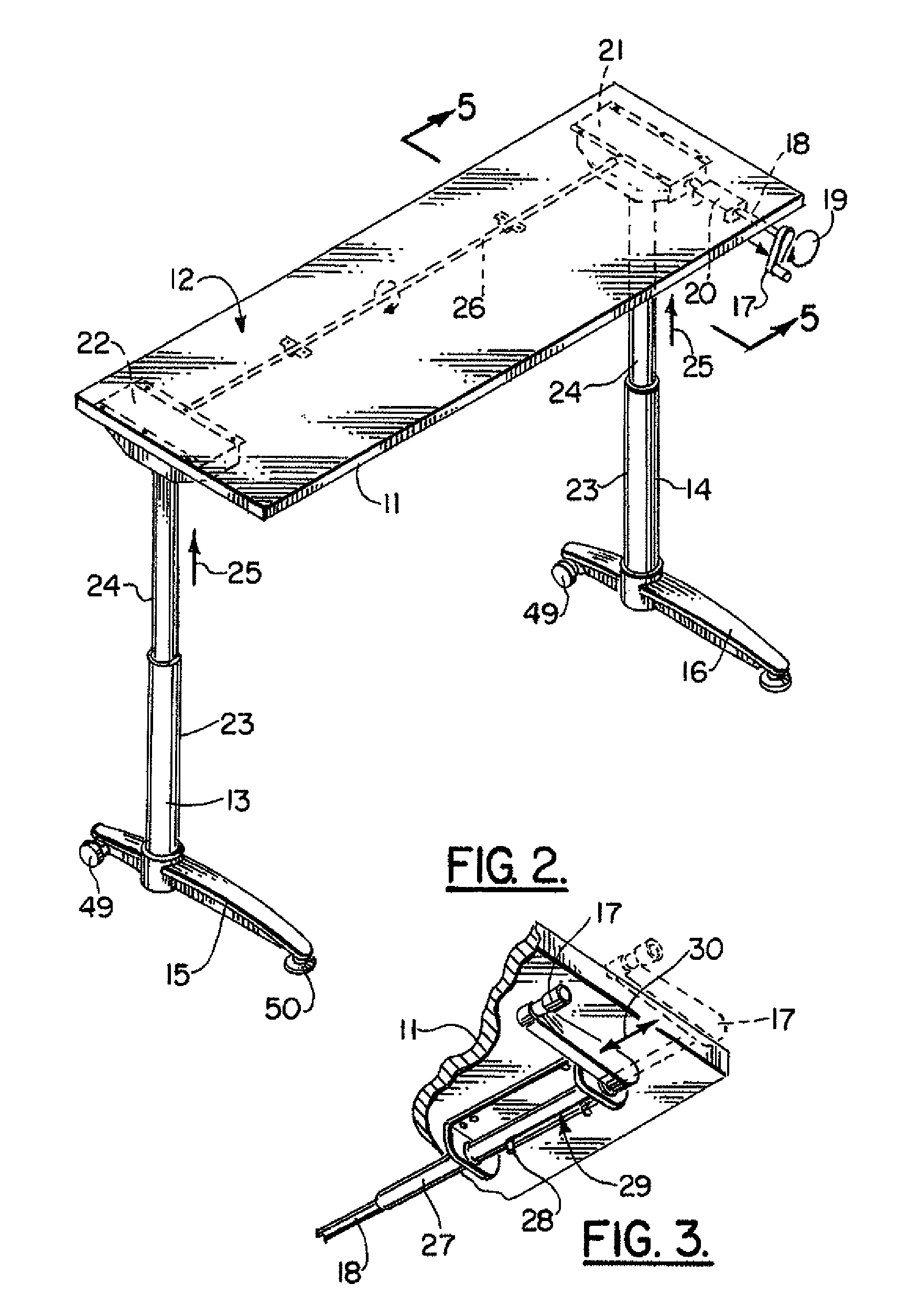
[0054]FIGS. 14 and 15 show the apparatus of the present invention, designated generally by the numeral 10A. Height adjustable table 10A is similar to the preferred embodiment of FIGS. 1-13. In FIGS. 14 and 15 however, a curved expansive top 11A is provided having a work surface 12A. Height adjustable table 10A provides three legs 13, 14, 80. Each of the legs 13, 14, 80 can be constructed in accordance with the preferred embodiment of FIGS. 1-13. The leg 80 provides a single wheeled caster 49, while the feet 15, 16 can provide either a caster 49 or a fixed support 50 as shown in FIG. 6.
[0055]In FIG. 15, height adjustable table 10A provides three gear box housings 21, 22 and 69. The gear box housings 21, 22 are constructed in accordance with the preferred embodiment of FIGS. 1-13. The gear box 69 forms an interface between two rods 67, 68. This arrangement is similar to that shown in FIG. 7. However, the rods 67, 68 form an obtuse angle as opposed to a ninety degree or right angle. In...
third embodiment
[0056]FIGS. 16-19 and 22-23 show the apparatus of the present invention, designated generally by the numeral 10C. Height adjustable table 10C employs a telescoping leg 70 that can be used for a two-legged table (FIG. 18), a three-legged table (FIG. 22), or a table having more than three legs (FIG. 23). In FIG. 16, telescoping leg 70 includes an upper elevating section 71 and a lower static section 72. A third leg section is an outer tube 73 that is also static and that surrounds the combination of upper elevating section 71 and lower static section 72. This arrangement of the three sections can be seen in FIGS. 16 and 17.
[0057]Externally threaded shaft 75 extends from gear box housing 79 downwardly to internally threaded nut 74 which is mounted in the upper end portion of lower static section 72, as shown in FIG. 17. The lower end of externally threaded shaft 75 provides a stop 76. When elevating the table 10C, expansive top 81 and its work surface 82, a maximum elevation is reached...
PUM
 Abstract
Description
Claims
Application Information
 - R&D
- Intellectual Property
- Life Sciences
- Materials
- Tech Scout
- Unparalleled Data Quality
- Higher Quality Content
- 60% Fewer Hallucinations
Browse by: Latest US Patents, China's latest patents, Technical Efficacy Thesaurus, Application Domain, Technology Topic, Popular Technical Reports.
© 2025 PatSnap. All rights reserved.Legal|Privacy policy|Modern Slavery Act Transparency Statement|Sitemap|About US| Contact US: help@patsnap.com


