Artificial spinal disk

a spinal disc and artificial technology, applied in the field of orthopedic surgery, can solve the problems of no stability of the spine in applications, no significant movement of the vertebrae involved, and the spinal musculature does little to stabilize the articulation of the facet joint,

Inactive Publication Date: 2011-03-22
ZIELINSKI STEVEN C
View PDF36 Cites 6 Cited by
  • Summary
  • Abstract
  • Description
  • Claims
  • Application Information

AI Technical Summary

Benefits of technology

[0009]Accordingly, it is an object of the present invention to provide an artificial spinal disk for stabilizing spinal vertebrae.
[0011]Still another object of the invention is to provide an artificial spinal disk for stabilizing spinal vertebrae while permitting significant motion of the stabilized vertebrae in situations where there is little muscle, ligament or bone structure to support the vertebrae.
[0014]In another aspect of the invention and in accordance with its objects and purposes, the artificial spinal disk for placement between adjacent spinal vertebrae to replace disk material, hereof, includes in combination: a first flat plate for attaching to the endplate of a first vertebral body, the first flat plate having a first surface and an opposing second surface, a front wall, and a slot opening through the second surface and through the front wall; a second flat plate having a first surface and an opposing second surface, and adapted to slide into the slot in the first plate; a post having a first end, and a second end perpendicularly attached to the second surface of the second plate and extending through the slot opening in the second flat surface of the first plate; a ball having a portion of the spherical surface thereof transitioned into a conical portion, wherein the smaller end of the conical portion is mounted on the first end of the post; means for rigidly affixing the second plate to the first plate; a third member having a first surface, an opposing second surface, and a front wall, the first surface being adapted to be attached to the endplate of a second vertebral body opposing the endplate of the first vertebral body, the third member having a slot therein opening through the second surface and through the front wall thereof and a first channel within the slot opening through the front wall of the third member adapted to slidably and rotatably receive the ball; a fourth member having a first surface, a second opposing surface, and a rear wall, and adapted to slide into the slot in the third member, the second surface having a second channel therein adapted to slidably and rotatably receive the ball, and opening through the rear wall; and means for rigidly affixing the fourth member to the third member, whereby the channel in the third member and the channel in the fourth member form opposing, parallel channels, wherein the ball may rotate and slide a chosen distance therein.
[0016]In still another aspect of the invention and in accordance with its objects and purposes, the artificial spinal disk for placement between adjacent spinal vertebrae to replace disk material, hereof, includes in combination: a first flat plate for attaching to the endplate of a first vertebral body the first flat plate having a first surface and an opposing second surface; a post having a first end, and a second end perpendicularly attached to the second surface of the first plate; a ball having a portion of the spherical surface thereof transitioned into a conical portion, wherein the smaller end of the conical portion is mounted on the first end of the post; a second member having a first surface, an opposing second surface, and a front wall, the first surface adapted to be attached to the endplate of a second vertebral body opposing the endplate of the first vertebral body, the second member having a slot therein opening through the second surface and through the front wall thereof and a first channel within the slot opening through the front wall of the second member adapted to slidably and rotatably receive the ball; a third member having a first surface, an opposing second surface, and a rear wall, and adapted to slide into the slot in the second member, the second surface having a second channel therein adapted to slidably and rotatably receive the ball, and opening through the rear wall; and means for rigidly affixing the third member to the second member, whereby the channel in the second member and the channel in the third member form opposing, parallel channels wherein the ball may rotate and slide a chosen distance therein.
[0017]Benefits and advantages of the present invention include, but are not limited to, providing an artificial spinal disk for insertion between two adjacent spinal vertebrae, portions of which may be removed for repair or replacement without damaging the spinal vertebrae. Additionally the spinal implant hereof may be assembled from the front of the spine as individual component parts, thereby permitting alignment of the spine during the assembly process, and the stabilization of the involved vertebrae once assembly has been completed. Further, the components may be chosen from a set of similar components having different sizes, thereby enabling the implant to be tailor fit to the requirements of the patient.

Problems solved by technology

It is known that spinal musculature does little to stabilize facet joint articulation in the spine.
With the exceptions of the '065 and the '644 patents, the above patents and patent applications provide no stability to the spine in the situation where stability is not provided by existing ligaments.
The '065 patent does not permit significant movement of the vertebrae involved.
This design does not permit lateral movement between the plates.

Method used


Image

  • Artificial spinal disk
  • Artificial spinal disk
  • Artificial spinal disk

Examples


Embodiment Construction

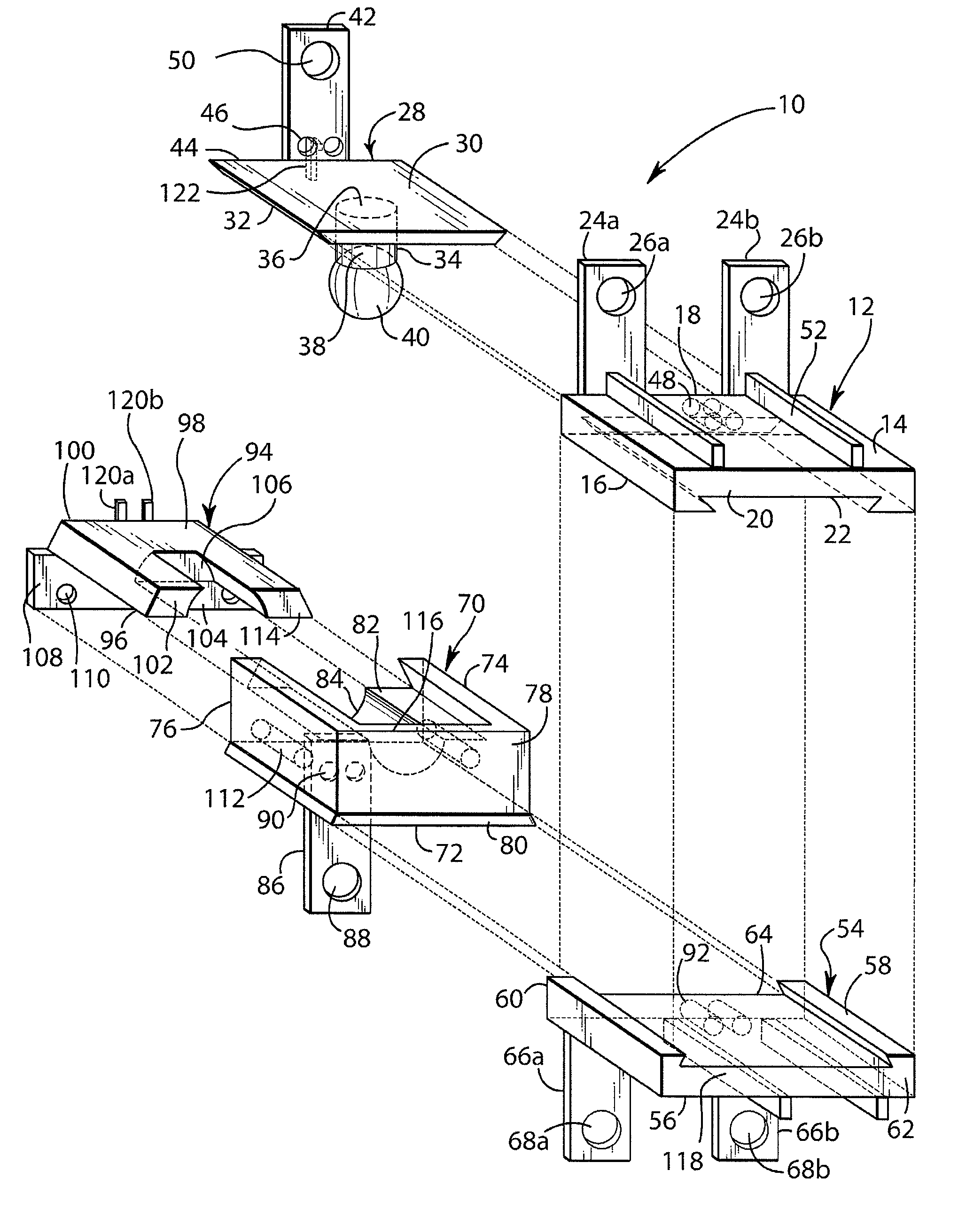
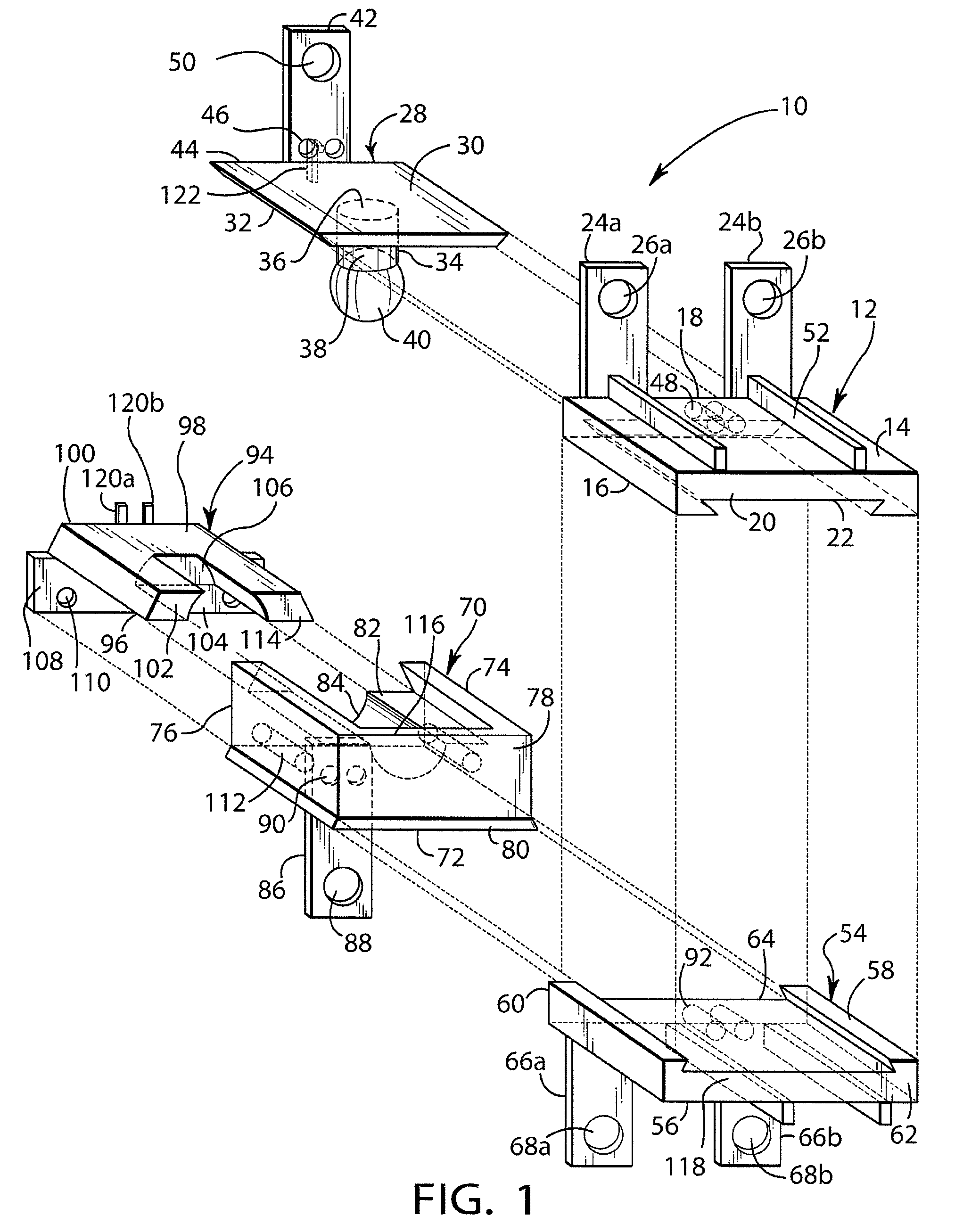
[0027]Briefly, the present invention includes an artificial spinal implant for placement between adjacent vertebrae to replace disk material and stabilize vertebrae involved. The component parts of the implant may be assembled in the space between the vertebrae during surgery as individual components which permits each implant to be tailored to the requirements of the patient. This also permits the spine to be aligned during assembly of the components, the involved vertebrae being stabilized when the assembly is complete. The assembled implant allows controlled anterior / posterior motion of the vertebrae as well as relative rotation thereof and bending therebetween.

[0028]Reference will now be made in detail to the present embodiments of the invention, examples of which are illustrated in the accompanying drawings. In the Figures, similar structure will be identified using identical reference characters. Turning now to FIG. 1, a schematic representation of an exploded view of one embo...


PUM


Abstract

An artificial spinal implant for placement between adjacent vertebrae to replace disk material and to stabilize the involved vertebrae is described. The artificial disk may be disassembled for installation and / or removal for repair, replacement or adjustment, and may be assembled from the front of the spine as individual component parts, thereby permitting alignment of the spine during the assembly process, and the stabilization of the involved vertebrae once assembly has been completed. Further, the components may be chosen from a set of similar components having different sizes, thereby enabling the implant to be tailor fit to the requirements of the patient.

Description

RELATED CASES[0001]The present patent application is a continuation-in-part patent application of copending U.S. patent application Ser. No. 12 / 022,947 for “ARTIFICIAL SPINAL DISK” by Steven C. Zielinski which was filed on Jan. 30, 2008, the disclosure and teachings of which are hereby incorporated by reference herein.FIELD OF THE INVENTION[0002]The present invention relates generally to orthopedic surgery and, more particularly, to artificial spinal implants for insertion between spinal vertebrae which may be used to replace ruptured or excised spinal disks and to stabilize the spine.BACKGROUND OF THE INVENTION[0003]It is known that spinal musculature does little to stabilize facet joint articulation in the spine. This function is provided by the ligament structure. Most artificial disk replacements today are for degenerate disks which are causing pain. The bone, muscle and the ligaments are all intact, and the spine itself is stable. When a spine is unstable and the bones and liga...

Claims


Application Information

Patent Timeline
Patent Type & Authority Patents(United States)
IPC IPC(8): A61F2/44
CPCA61F2/4425A61F2002/30242A61F2002/30369A61F2002/30387A61F2002/30405A61F2002/30433A61F2002/30517A61F2002/30578A61F2002/30604A61F2002/30649A61F2002/30884A61F2220/0025A61F2220/0033A61F2220/0041A61F2230/0071
Inventor ZIELINSKI, STEVEN C.
Owner ZIELINSKI STEVEN C
Why Eureka
Try Eureka