[0008]Accordingly, it is an object of the present invention to provide an artificial spinal disk for stabilizing spinal vertebrae.
[0010]Still another object of the invention is to provide an artificial spinal disk for stabilizing spinal vertebrae while permitting significant motion of the stabilized vertebrae in situations where there is little
muscle,
ligament or
bone structure to support the vertebrae.
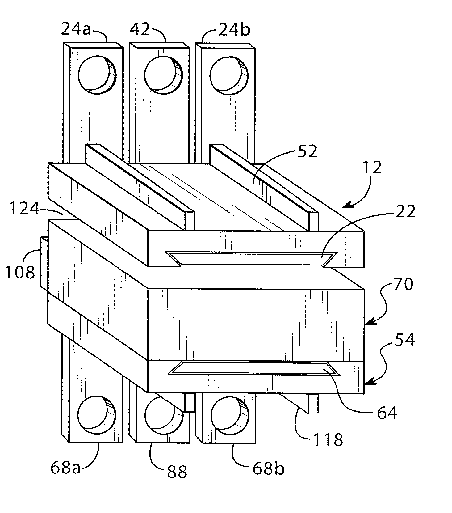
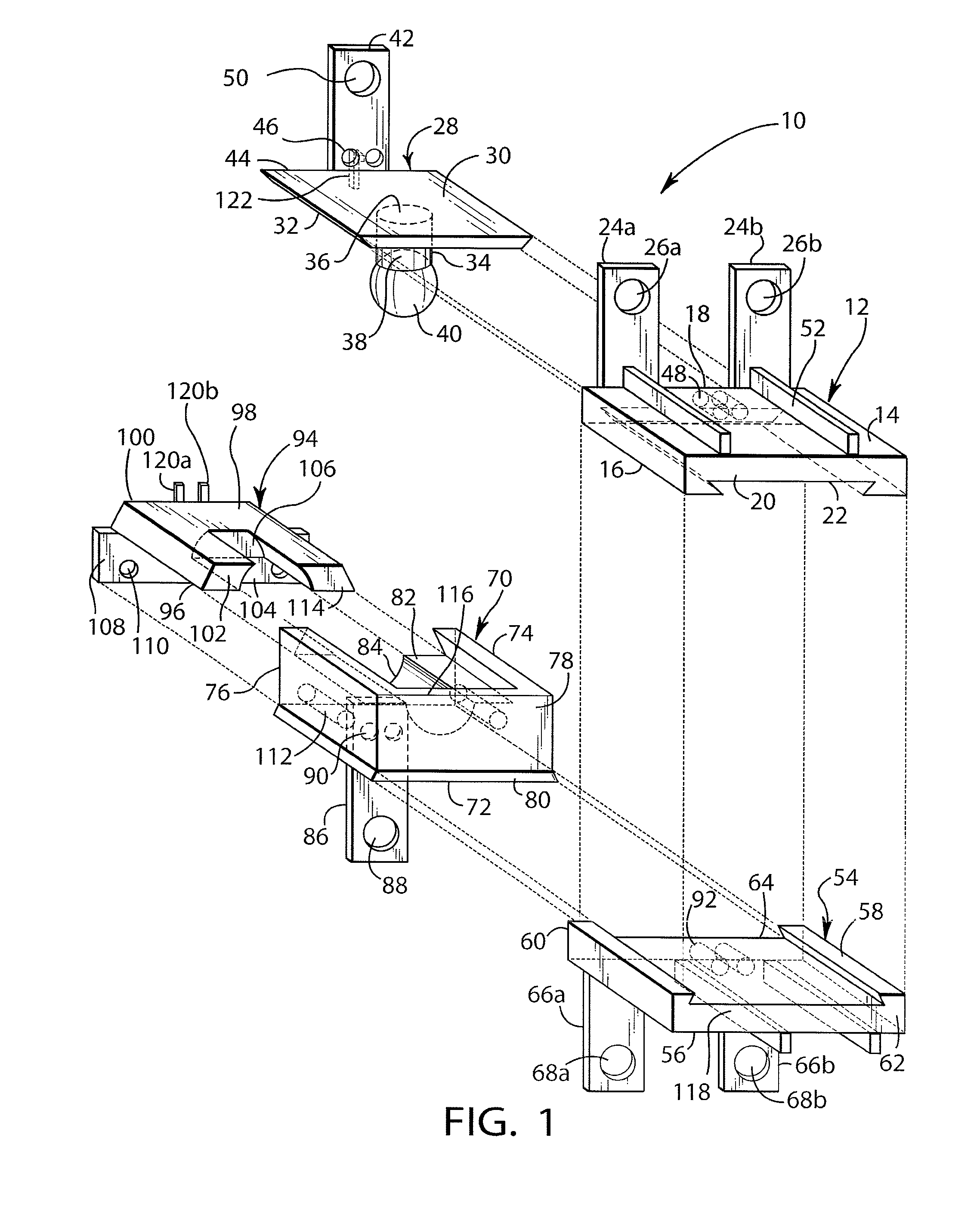
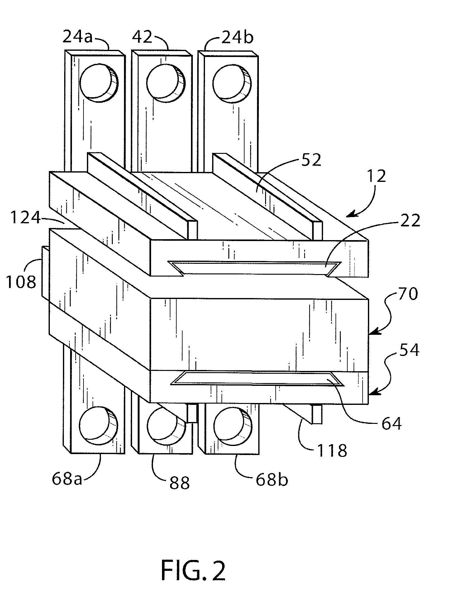
[0013]In another aspect of the invention and in accordance with its objects and purposes, the artificial spinal disk for placement between adjacent spinal vertebrae to replace disk material, hereof, includes in combination: a first flat plate for attaching to the endplate of a first
vertebral body, the first flat plate having a first surface and an opposing second surface, a front wall, and a slot opening through the second surface and through the front wall; a second flat plate having a first surface and an opposing second surface, and adapted to slide into the slot in the first plate; a post having a first end, and a second end perpendicularly attached to the second surface of the second plate and extending through the slot opening in the second flat surface of the first plate; a ball mounted on the first end of the post; means for rigidly affixing the second plate to the first plate; a third member having a first surface, an opposing second surface, and a front wall, the first surface being adapted to be attached to the endplate of a second
vertebral body opposing the endplate of the first
vertebral body, the third member having a slot therein opening through the second surface and through the front wall thereof and a first channel within the slot opening through the front wall of the third member adapted to slidably and rotatably receive the ball; a fourth member having a first surface, a second opposing surface, and a rear wall, and adapted to slide into the slot in the third member, the second surface having a second channel therein adapted to slidably and rotatably receive the ball, and opening through the rear wall; and means for rigidly affixing the fourth member to the third member, whereby the channel in the third member and the channel in the fourth member form opposing, parallel channels, wherein the ball may rotate and slide a chosen distance therein.
[0015]In still another aspect of the invention and in accordance with its objects and purposes, the artificial spinal disk for placement between adjacent spinal vertebrae to replace disk material, hereof, includes in combination: a first flat plate for attaching to the endplate of a first vertebral body the first flat plate having a first surface and an opposing second surface; a post having a first end, and a second end perpendicularly attached to the second surface of the first plate; a ball mounted on the first end of the post; a second member having a first surface, an opposing second surface, and a front wall, the first surface adapted to be attached to the endplate of a second vertebral body opposing the endplate of the first vertebral body, the second member having a slot therein opening through the second surface and through the front wall thereof and a first channel within the slot opening through the front wall of the second member adapted to slidably and rotatably receive the ball; a third member having a first surface, an opposing second surface, and a rear wall, and adapted to slide into the slot in the second member, the second surface having a second channel therein adapted to slidably and rotatably receive the ball, and opening through the rear wall; and means for rigidly affixing the third member to the second member, whereby the channel in the second member and the channel in the third member form opposing, parallel channels wherein the ball may rotate and slide a chosen distance therein.
[0016]Benefits and advantages of the present invention include, but are not limited to, providing an artificial spinal disk for
insertion between two adjacent spinal vertebrae, portions of which may be removed for repair or replacement without damaging the spinal vertebrae. Additionally the
spinal implant hereof may be assembled from the front of the spine as individual component parts, thereby permitting alignment of the spine during the
assembly process, and the stabilization of the involved vertebrae once assembly has been completed. Further, the components may be chosen from a set of similar components having different sizes, thereby enabling the
implant to be tailor fit to the requirements of the patient.

