

Method and system for providing optical proximity correction for structures such as a PMR nose
- Summary
- Abstract
- Description
- Claims
- Application Information
AI Technical Summary
Benefits of technology
Problems solved by technology
Method used
Image

Examples
Embodiment Construction
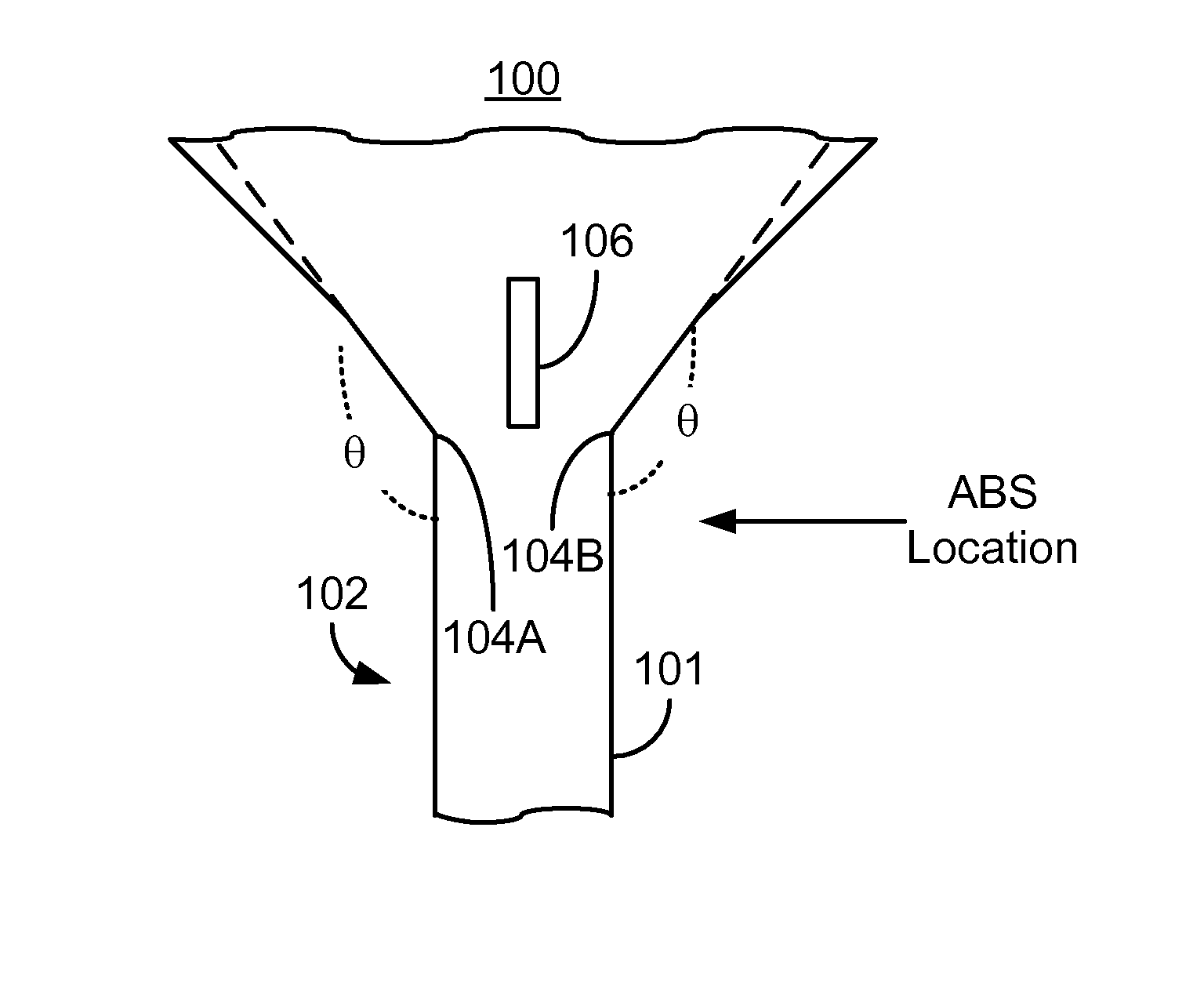
[0020]FIG. 5 depicts an exemplary embodiment of an optical mask 100 used in fabricating electronic devices having a corner, such as a PMR pole of a magnetic transducer. For clarity, FIG. 5 is not drawn to scale. In the embodiment shown, the optical mask 100 is used in fabricating the PMR pole. However, in other embodiments, the optical mask 100 may be used in fabricating other electronic devices. The mask 100 is termed an optical mask because electromagnetic radiation is used in connection with the optical mask 100. Consequently, the optical mask 100 need not be limited to use with the visible spectrum. The optical mask 100 includes a pattern for providing the device. For example, in the embodiment shown, the pattern includes a device feature 101. The edges of the device feature 101 are shown in solid lines. The device feature 101 shown is opaque and may be formed of a material such as Cr on an underlying quartz substrate. The remaining portions of the mask 100 shown may be transpar...
PUM
 Abstract
Description
Claims
Application Information