
Semiconductor device and associated layouts having transistors formed from six linear conductive segments with gate electrode connection through single interconnect level

a technology of linear conductive segments and semiconductor devices, which is applied in the direction of cad circuit design, semiconductor/solid-state device details, instruments, etc., can solve the problems of inadvertent removal of desired shapes, inadvertent creation of unwanted shapes, and inability to meet the needs of the user

Inactive Publication Date: 2011-03-22
RPX CORP
View PDF260 Cites 111 Cited by
  • Summary
  • Abstract
  • Description
  • Claims
  • Application Information

AI Technical Summary

Benefits of technology

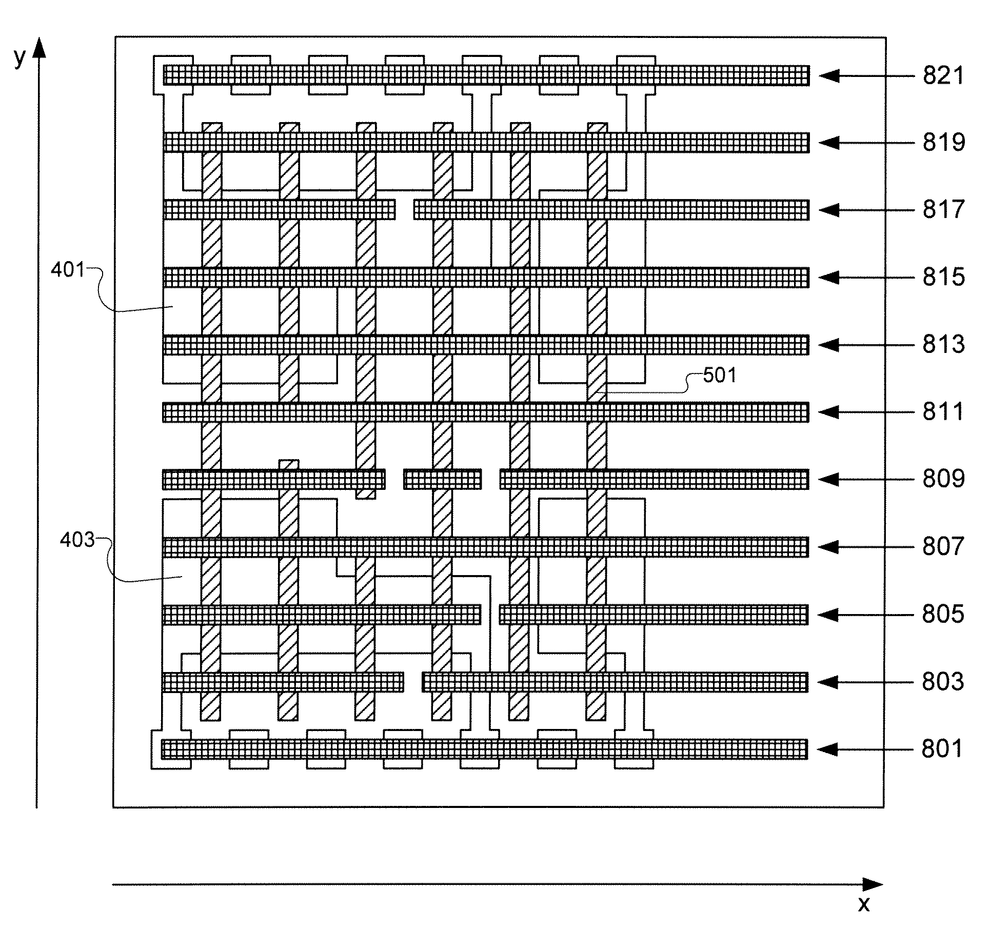
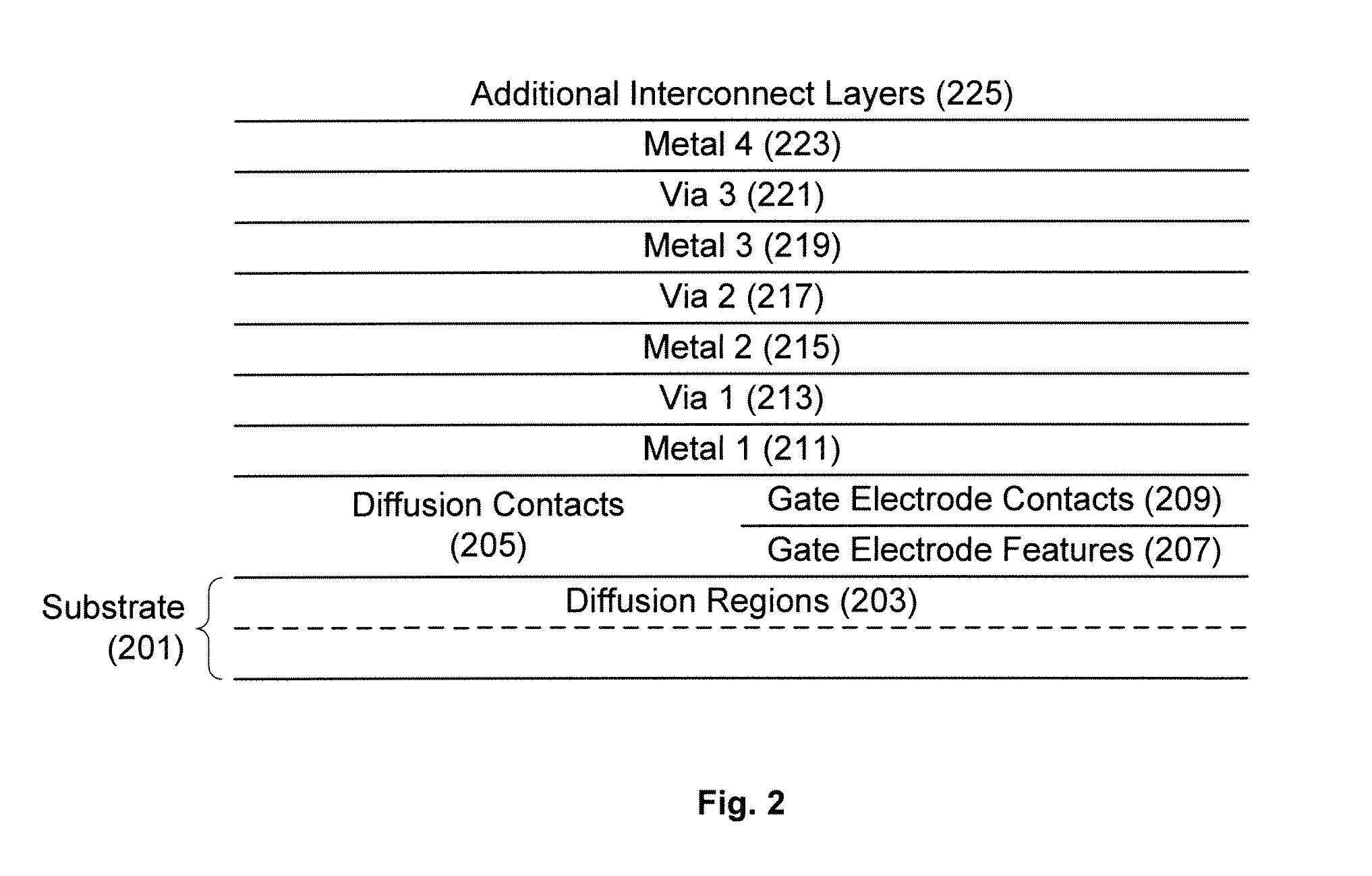
The patent describes a layout for a semiconductor device that includes a diffusion level layout and a gate electrode level layout. The diffusion level layout includes a plurality of diffusion region layout shapes that correspond to active areas of the device. The diffusion region layout shapes are separated from each other by non-active regions. The gate electrode level layout includes a number of linear-shaped layout features placed to extend in only a first parallel direction. The layout also includes interconnect level layouts that pattern conductive features within interconnect levels above the gate electrode level. The layouts are designed to spatially relate to connect as required to form one or more functional electronic devices of the device. The technical effect of the invention is to provide a precise layout for the semiconductor device that facilitates the fabrication of complex integrated circuits.

Problems solved by technology

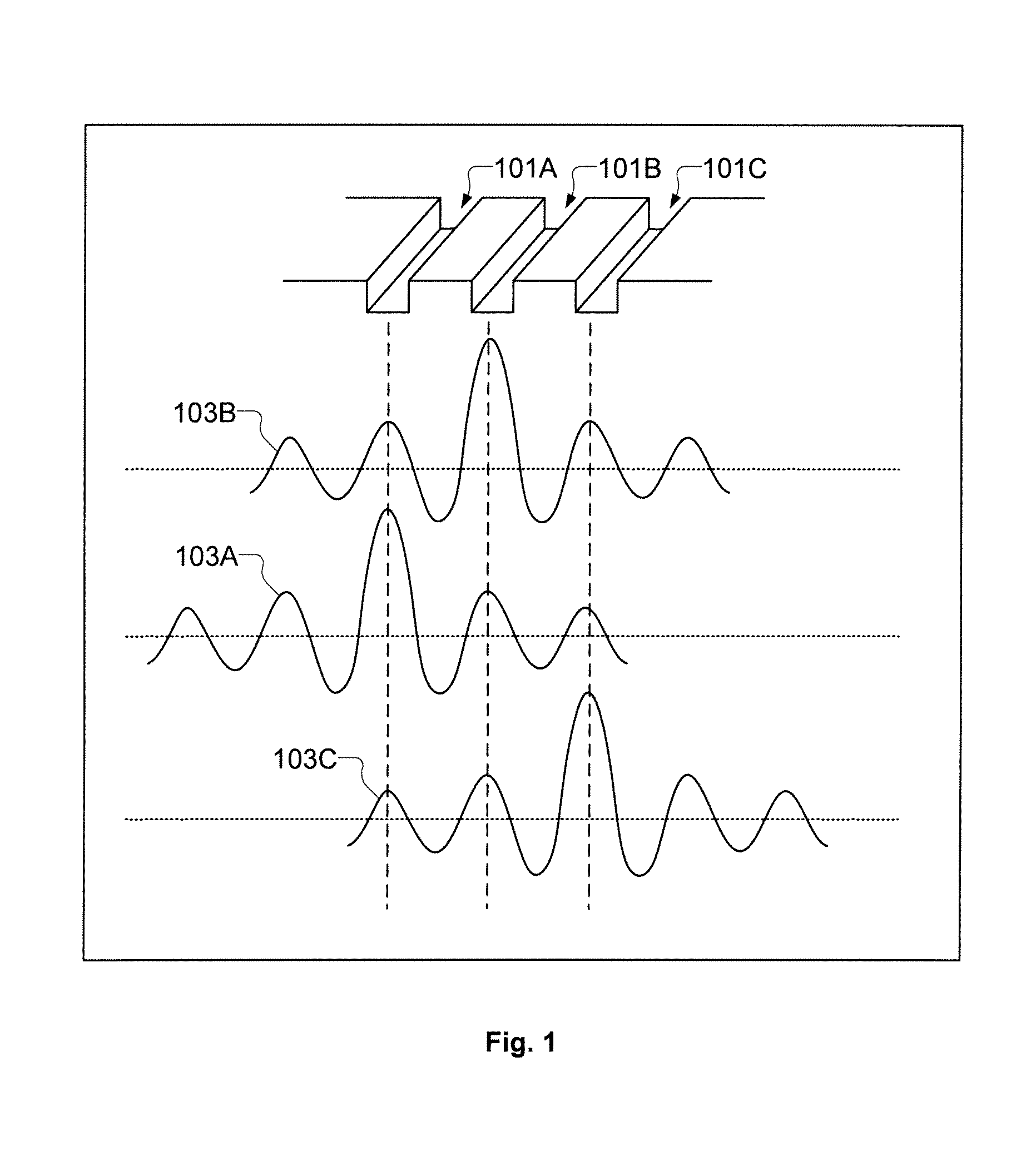
The interference patterns from neighboring shapes can create constructive or destructive interference.
In the case of constructive interference, unwanted shapes may be inadvertently created.
In the case of destructive interference, desired shapes may be inadvertently removed.
In either case, a particular shape is printed in a different manner than intended, possibly causing a device failure.
The quality of the light interaction prediction is declining as process geometries shrink and as the light interactions become more complex.

Method used


Image

  • Semiconductor device and associated layouts having transistors formed from six linear conductive segments with gate electrode connection through single interconnect level
  • Semiconductor device and associated layouts having transistors formed from six linear conductive segments with gate electrode connection through single interconnect level
  • Semiconductor device and associated layouts having transistors formed from six linear conductive segments with gate electrode connection through single interconnect level

Examples


Embodiment Construction

[0034]In the following description, numerous specific details are set forth in order to provide a thorough understanding of the present invention. It will be apparent, however, to one skilled in the art that the present invention may be practiced without some or all of these specific details. In other instances, well known process operations have not been described in detail in order not to unnecessarily obscure the present invention.

[0035]Generally speaking, a dynamic array architecture is provided to address semiconductor manufacturing process variability associated with a continually increasing lithographic gap. In the area of semiconductor manufacturing, lithographic gap is defined as the difference between the minimum size of a feature to be defined and the wavelength of light used to render the feature in the lithographic process, wherein the feature size is less than the wavelength of the light. Current lithographic processes utilize a light wavelength of 193 nm. However, cur...


PUM


Abstract

A cell layout of a semiconductor device includes a diffusion level layout including a plurality of diffusion region layout shapes. The cell layout also includes a gate electrode level layout defined to include linear-shaped layout features placed to extend in only a first parallel direction. Adjacent linear-shaped layout features that share a common line of extent in the first parallel direction are separated from each other by an end-to-end spacing that is substantially equal across the gate electrode level layout and that is minimized to an extent allowed by a semiconductor device manufacturing capability. The gate electrode level layout includes linear-shaped layout features defined along at least four different lines of extent in the first parallel direction. The cell layout also includes a number of interconnect level layouts each defined to pattern conductive features within corresponding interconnect levels above the gate electrode level of the cell.

Description

CLAIM OF PRIORITY[0001]This application is a continuation application under 35 U.S.C. 120 of prior U.S. application Ser. No. 12 / 212,562, filed Sep. 17, 2008, now U.S. Pat. No. 7,842,975 and entitled “Dynamic Array Architecture,” which is a continuation application under 35 U.S.C. 120 of prior U.S. application Ser. No. 11 / 683,402, filed Mar. 7, 2007, now U.S. Pat. No. 7,446,352 and entitled “Dynamic Array Architecture,” which claims priority under 35 U.S.C. 119(e) to U.S. Provisional Patent Application No. 60 / 781,288, filed Mar. 9, 2006. Each of the above-identified applications is incorporated herein by reference in its entirety.CROSS-REFERENCE TO RELATED APPLICATIONS[0002]This application is related to each application identified in the table below. The disclosure of each application identified in the table below is incorporated herein by reference in its entirety.[0003]ApplicationFilingTitleNo.DateSemiconductor Device with Dynamic12 / 013,342Jan. 11, 2008Array SectionMethods for Des...

Claims


Application Information

Patent Timeline
Patent Type & Authority Patents(United States)
IPC IPC(8): H01L27/10
CPCH01L27/0207H01L27/092G06F17/5068H01L27/088H01L29/42372G06F17/5072H01L2924/0002H01L2924/00G06F30/39G06F30/392H01L21/823871H01L27/11807H01L2027/11888H01L23/5226H01L23/5283H01L29/42376H01L2027/11812H01L2027/11864H01L2027/11875H01L21/28123H01L2027/11855H01L2027/11861H01L2027/11862H01L2027/11866H01L2027/11887H01L2027/11814
Inventor BECKER, SCOTT T.SMAYLING, MICHAEL C.
Owner RPX CORP
Learn More