
Compact bolt cutter with improved mechanical advantage

a bolt cutter and compact technology, applied in the field of bolt cutters, can solve the problems of difficult for users to produce sufficient cutting force, long handles, and many consumers who are still unable to generate enough force to produce the desired cu

Active Publication Date: 2011-03-29
PELL IND
View PDF17 Cites 6 Cited by
  • Summary
  • Abstract
  • Description
  • Claims
  • Application Information

AI Technical Summary

Benefits of technology

The bolt cutter achieves a significant increase in cutting force, making it easier to use for larger materials without relying on user strength, resulting in a more compact, lighter, and less cumbersome tool that can efficiently cut or punch through steel bolts and reinforcement bars.

Problems solved by technology

However, many consumers are still unable to generate enough force to produce the desired cut.
One of the disadvantages to the existing devices is that the handles have to be made extremely long and it is still difficult for the user to be able to produce sufficient cutting force.
Also, existing devices are limited in their use to the force that can be applied directly by the user of the device.
And so the amount of force generated for cutting is limited by the physical strength of the user.
Further, the state of the art bolt cutters are heavy and cumbersome to use.

Method used


Image

  • Compact bolt cutter with improved mechanical advantage
  • Compact bolt cutter with improved mechanical advantage
  • Compact bolt cutter with improved mechanical advantage

Examples


Embodiment Construction

FIGS. 1, (1A &1B), 2, 3 and 4A and 4B

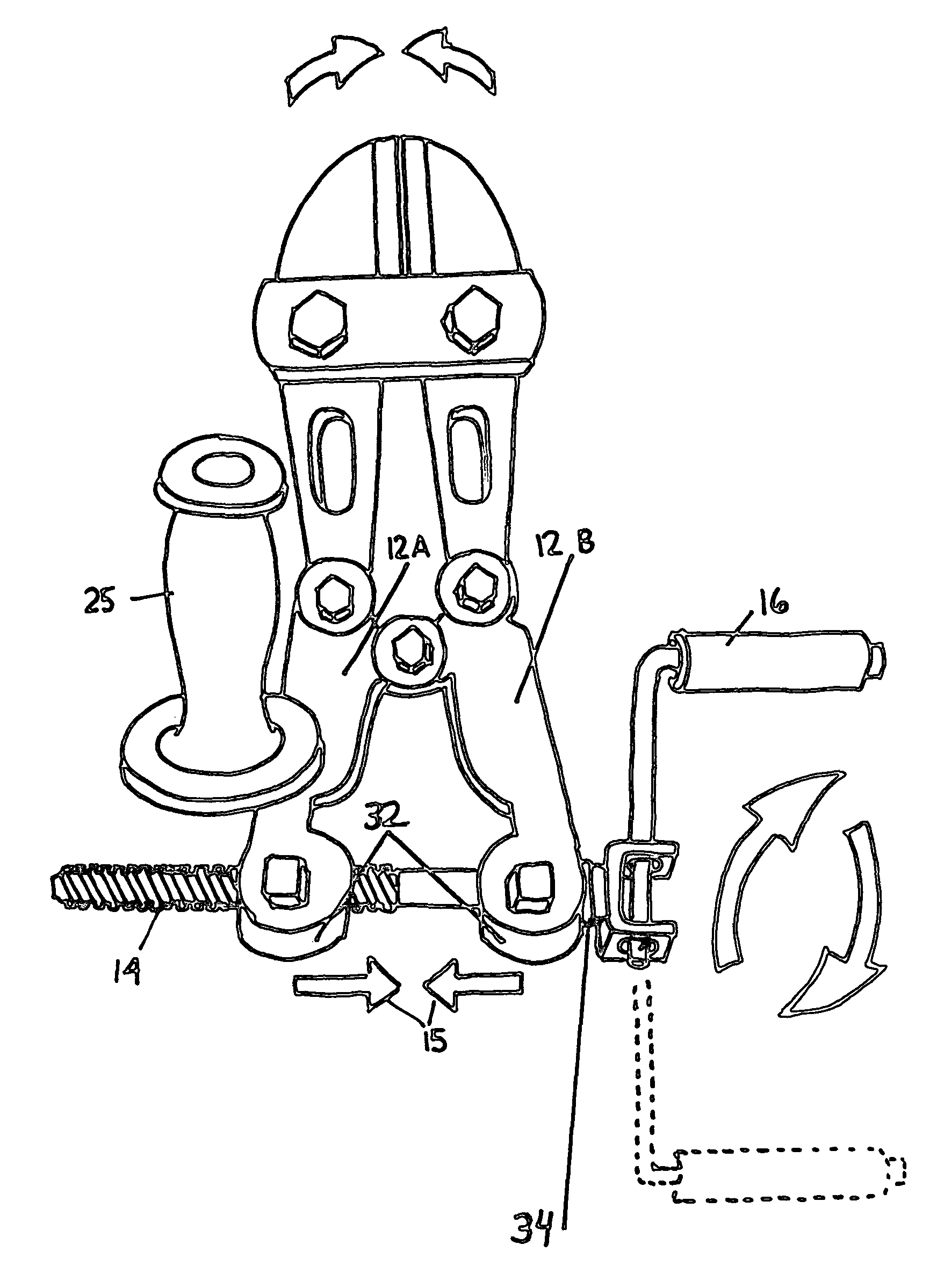
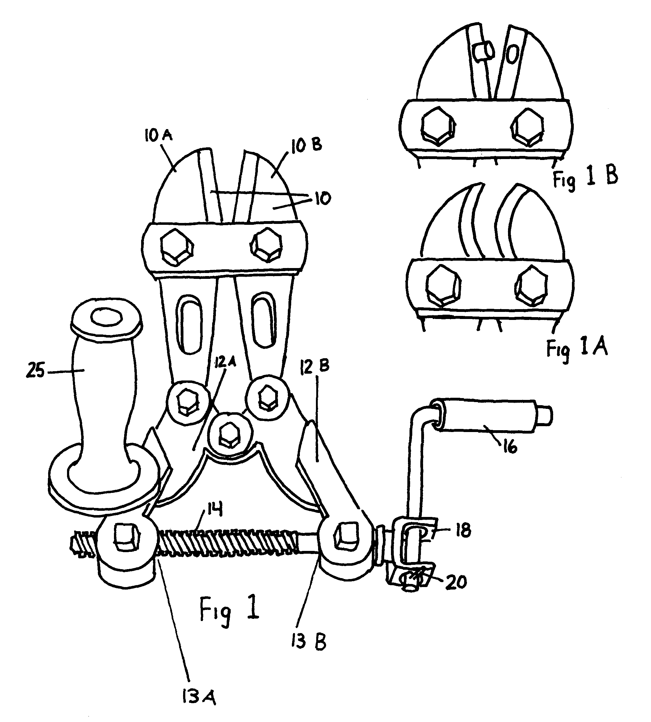
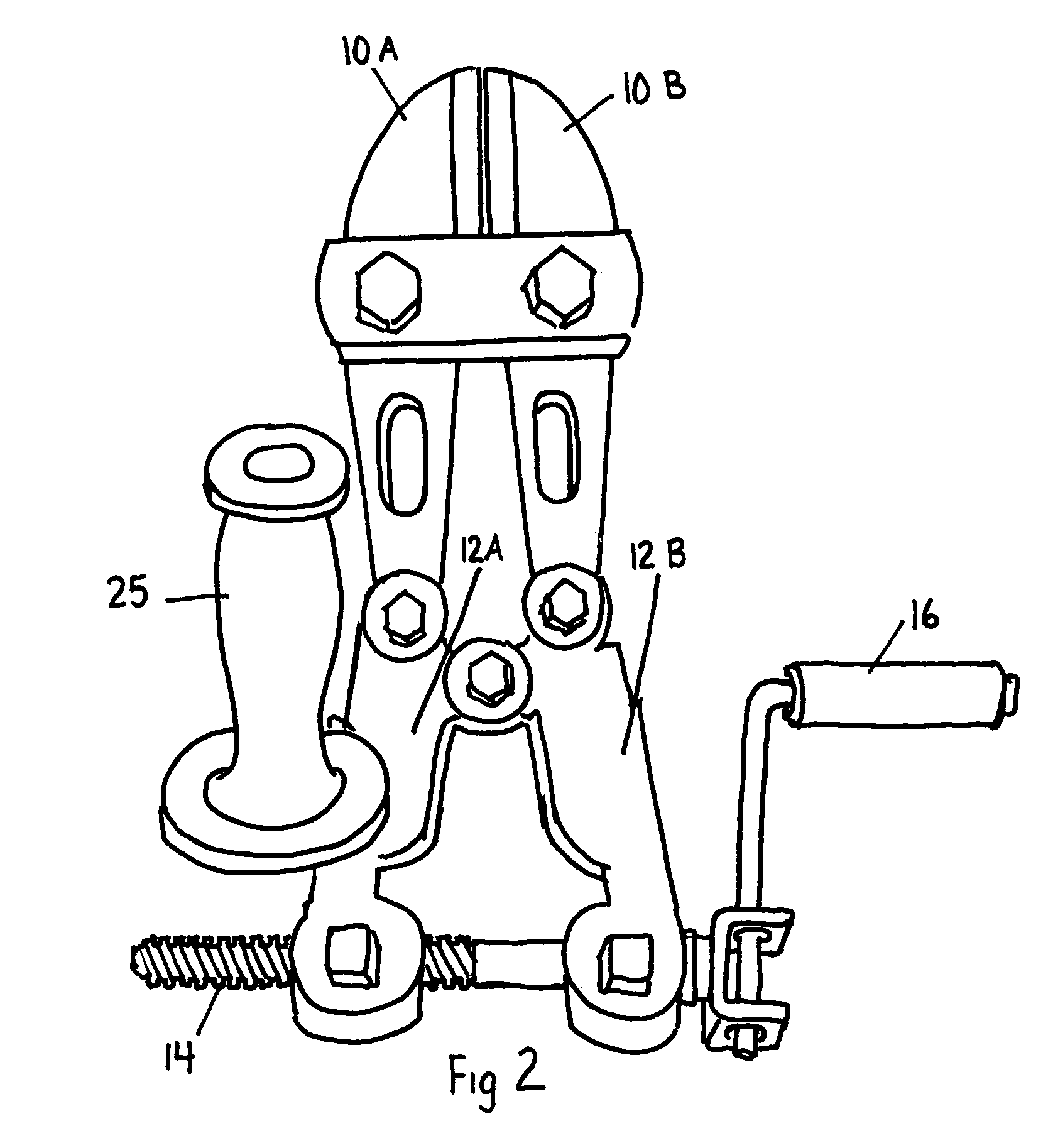
[0035]Reference is now made to the drawings illustrating one possible embodiment of the cutting tool of the present invention. As indicated previously, this tool can be used for cutting such as the cutting of bolts or can be used for cutting cables, locks, reinforcement bar or can even be used for a punching operation. The device is basically comprised of a set of jaws 10 including separate jaws 10A and 10B. Each of these jaws has a cutting blade and is supported for pivotal operation from the handles 12A and 12B. The basic cutting blades and handles 12A and 12B are like that found in existing instruments except that handles 12A and 12B are quite short in comparison to the conventional bolt cutter. When handles 12A and 12B are in a more open position such as shown in FIG. 1, this corresponds to an open position of cutting jaws 10.

[0036]At the base of handles 12A and 12B there is provided a tightening, lead or threaded rod 14 that functions simila...


PUM


Abstract

(FIG. 1) shows an improved bolt cutting tool comprising left and right cutting jaws (10) that are closed by handles (12A and 12B). As handles (12A and 12B) are separated, jaw (10) opens to allow the material to be cut to enter. The cutting handles (12A and 12B) are closed, utilizing a partially threaded rod (14) and rotational handle (16) to draw them closed. (FIG. 2).

Description

CROSS-REFERENCE TO RELATED APPLICATIONS[0001]This application claims the benefit of provisional application Ser. No. 60 / 879,485, filed 2007 Jan. 9 by the present inventor.FEDERALLY SPONSORED RESEARCH[0002]Not ApplicableSEQUENCE LISTING OR PROGRAM[0003]Not ApplicableBACKGROUND[0004]1. Field of Invention[0005]This invention relates in general to bolt cutters but may also apply to other devices for cutting or punching.[0006]2. Prior Art[0007]A commonly used conventional device for cutting bolts, locks, and reinforcement bar is referred to as a bolt cutter. The standard bolt cutter is generally made up of two long handles connected to a pair of opposing jaws that can be manually separated or brought together by movement of the handles. The long handles enable the user to produce force at the jaws for cutting, usually smaller sized bolts. This embodiment relates to a bolt cutter, type cutting tool, specifically with an improved closing mechanism.[0008]Originally bolt cutters were manufac...

Claims


Application Information

Patent Timeline
Patent Type & Authority Patents(United States)
IPC IPC(8): B26B17/00
CPCB26B17/02
Inventor LARKIN, JOHN ARTHUR
Owner PELL IND
Learn More