Row unit for an agricultural harvester

a technology for agricultural harvesters and row units, which is applied in the field of improving the grain head of the harvesting machine, can solve the problems of prone to bend or break of the row unit arms, which are camped forward from the frame of the harvesting head, and cannot permit the ears of corn to pass between and be los

Active Publication Date: 2011-03-29
DEERE & CO
View PDF4 Cites 50 Cited by
  • Summary
  • Abstract
  • Description
  • Claims
  • Application Information

AI Technical Summary

Problems solved by technology

And deck plates which are disposed on the upper surfaces of the arms define an adjustable gap that permits the plant stalks to be pulled downward and ejected into the ground but will not permit ears of corn to pass there between and be lost.
There are problems, however, with this arrangement.
When this happens, the row unit arms, which are camped levered forward from the frame of the harvesting head are prone to bend or break.

Method used


Image

  • Row unit for an agricultural harvester
  • Row unit for an agricultural harvester
  • Row unit for an agricultural harvester

Examples


Embodiment Construction

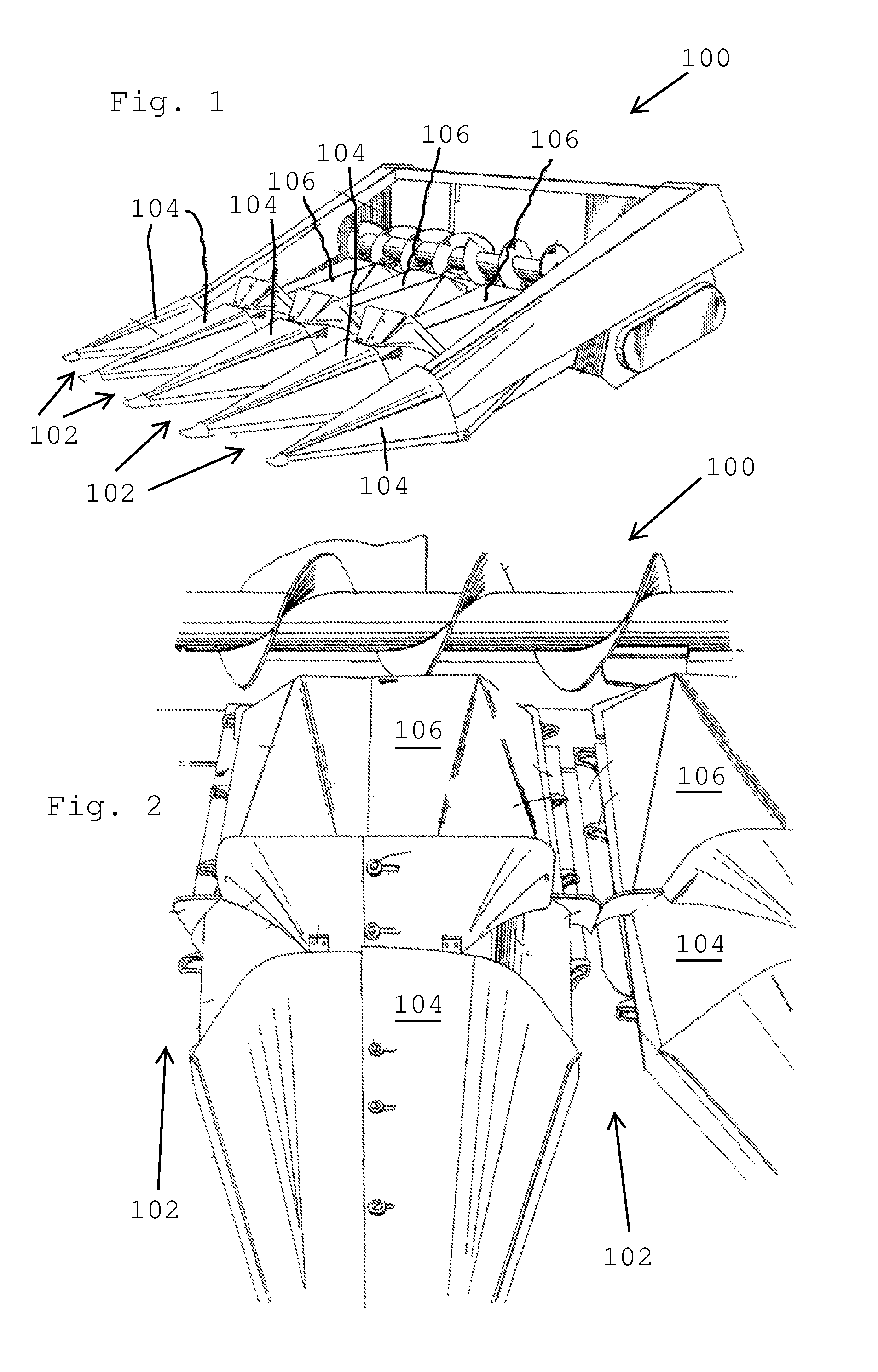
[0020]In FIGS. 1-2 there is illustrated a row crop head 100 having four row units 102 for the harvesting of crops, particularly corn. Points 104 and covers 106 (herein individually and collectively called “covers”) are disposed to rest on support brackets mounted on the front ends of the arms of each row unit and to cover portions of adjacent row units. The covers cover almost all of the row units 102 leaving only the gathering chains and deck plates exposed to receive the stalks of row crop plants. The corn head 100 is supported on a combine (not shown) which carries it through the field. The covers 106 are hinged at their rear ends to a hinge assembly that is mounted to two adjacent row units 102.

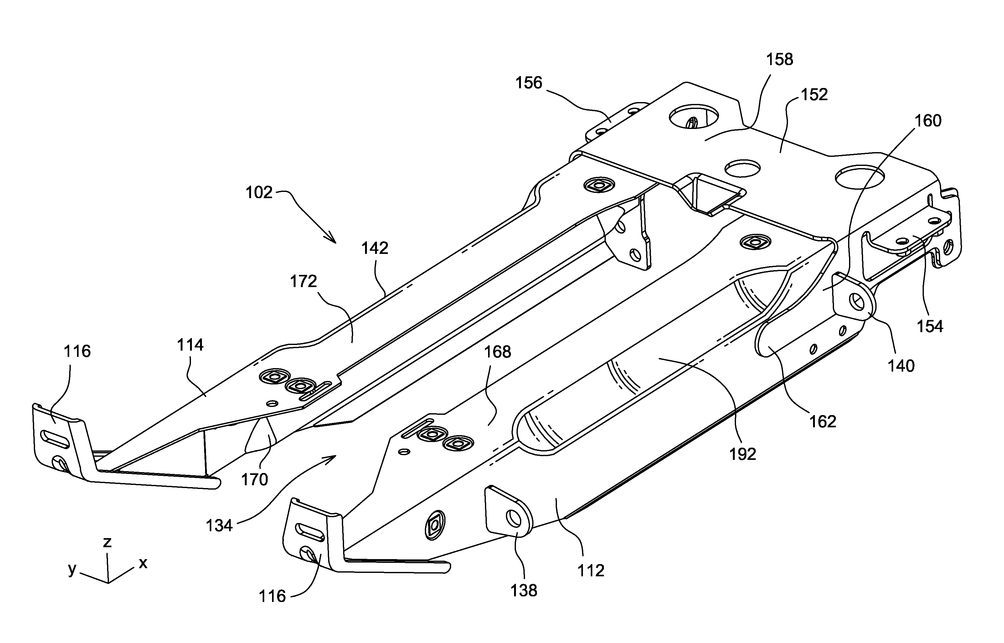
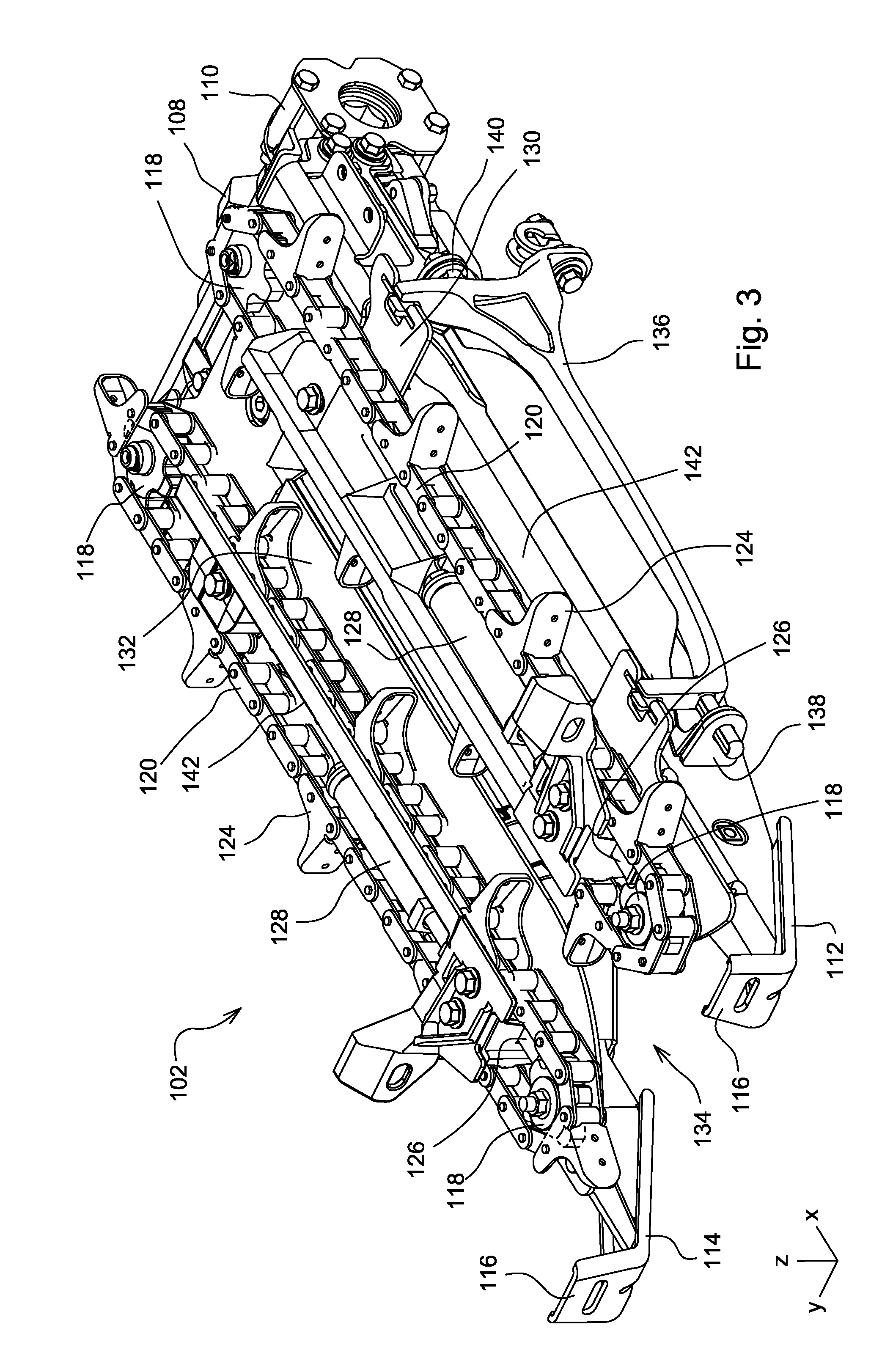
[0021]Referring now to FIG. 3, each row unit 102 includes a gearbox 108 and a clutch 110 attached to the rear portions of row unit arms 112, 114. Gearbox 108 and clutch 110 receive power from a row unit drive shaft, not shown, and then distribute the power in order to drive the various el...


PUM


Abstract

A row unit for an agricultural harvester includes left and right row unit arms that are fixed together with the shaped support. The shaped support is bent to extend across the top of the row unit arms and down the outside vertical surfaces of the row unit arms. The shaped support is welded to the outside vertical surfaces of the row unit arms.

Description

RELATED APPLICATIONS[0001]This application claims priority from, application No. 61 / 099,562, filed on Sep. 23, 2008, which is incorporated herein in its entirety for all that it teaches.FIELD OF THE INVENTION[0002]The present invention relates to improvements to a grain head for a harvesting machine.BACKGROUND OF THE INVENTION[0003]Harvesting heads for agricultural harvesters that are configured to harvest row crops typically have devices called row units. Row units are the mechanical assemblies that are configured to receive a row of crop plants, and to harvest them. Row units, such as cornrow units, also include structures to strip away part of the unwanted crop material, such as the plant's stalk.[0004]In its simplest configuration, a cornrow unit, such as the one illustrated herein, includes 2 elongate cantilevered arms that extend forwardly and generally horizontally in the direction of travel. These arms, fixed together at the rear of the arms, define a gap there between that ...

Claims


Application Information

Patent Timeline
Patent Type & Authority Patents(United States)
IPC IPC(8): A01D45/02
CPCA01D45/021
Inventor CHRISTENSEN, TIMOTHY FRANKLINBROWN, KENT STEPHEN
Owner DEERE & CO
Why Eureka
Try Eureka