
Sequencing diverter valve system for an appliance

a diverter valve and valve system technology, applied in the direction of cleaning using liquids, washing/rinsing machines of tableware, household cleaners, etc., can solve the problems of reducing the intensity of water jets, reducing the cleaning power, and limited spray arms fed by pumps, so as to increase the intensity of jets and sacrifice dwell time

Inactive Publication Date: 2011-03-29
WHIRLPOOL CORP
View PDF17 Cites 45 Cited by
  • Summary
  • Abstract
  • Description
  • Claims
  • Application Information

AI Technical Summary

Benefits of technology

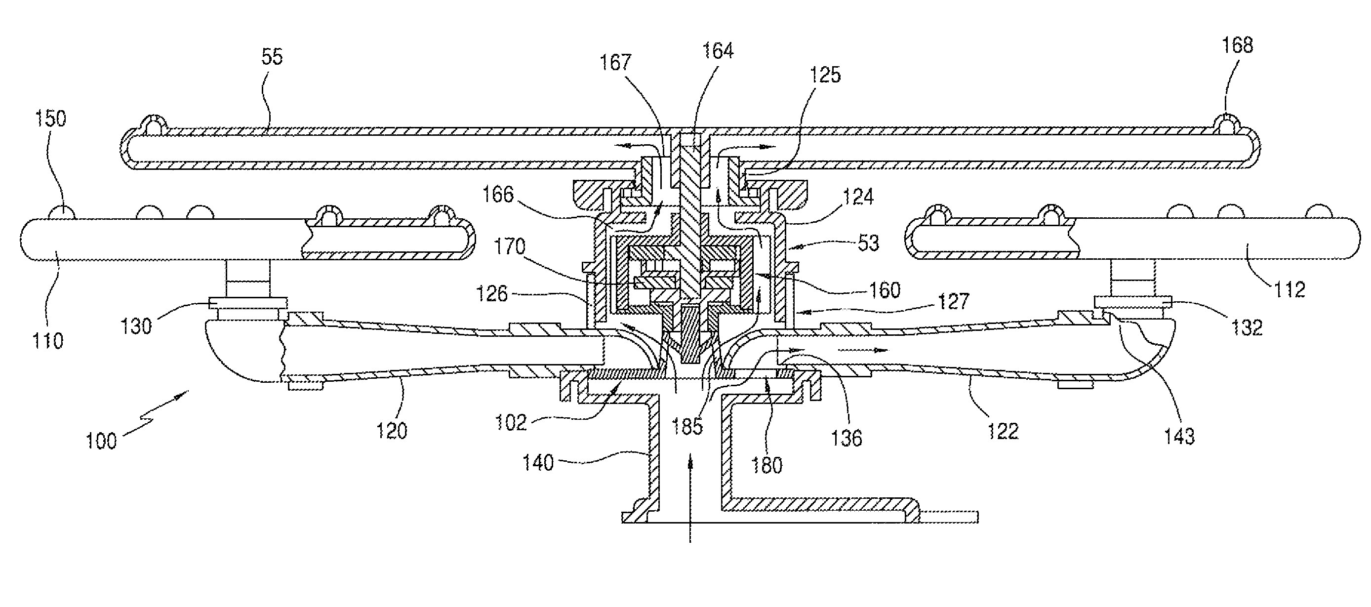
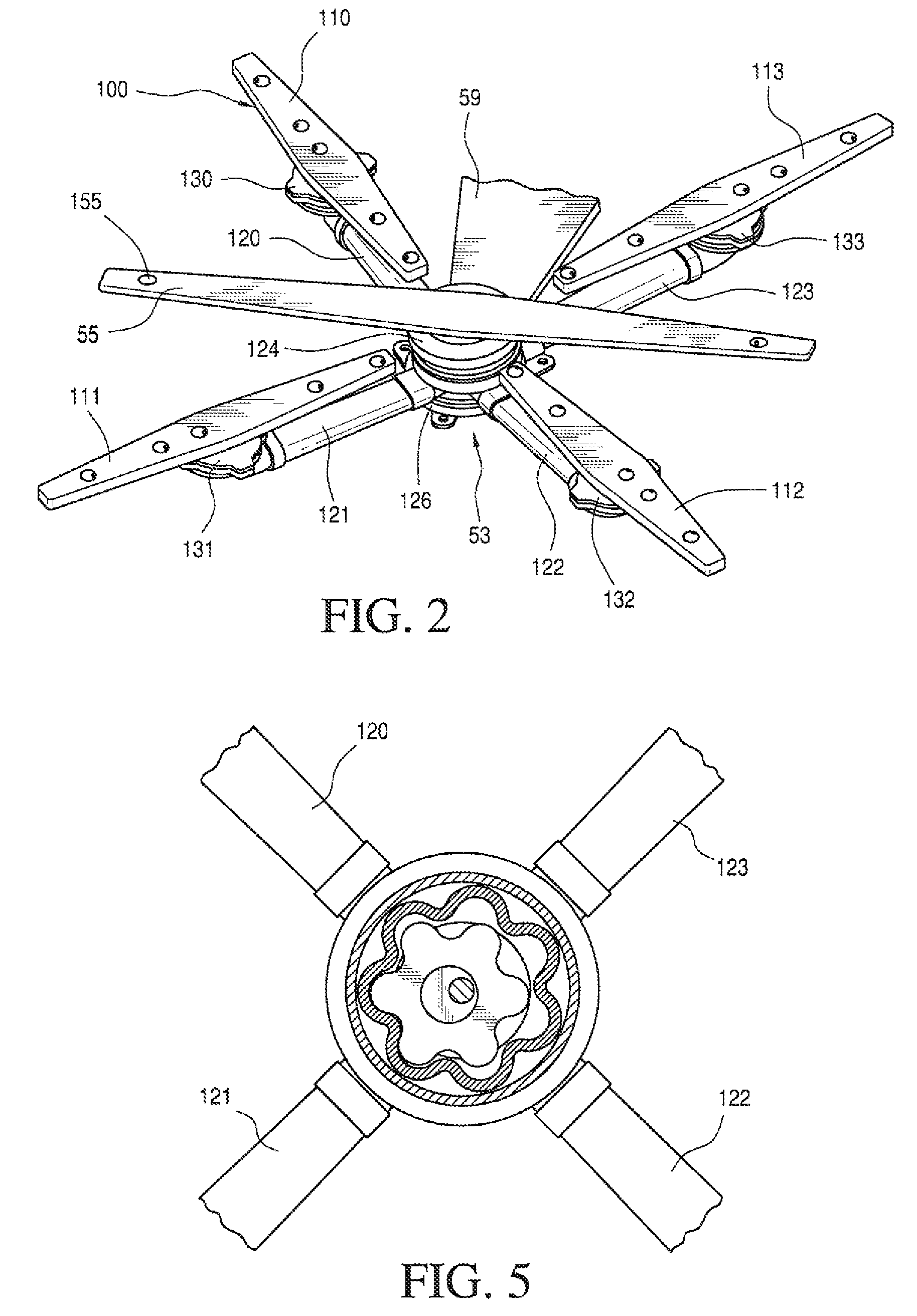
[0007]The present invention is directed to a washing appliance, such as a dishwasher or clothes washing machine, including a sequencing diverter valve system. In general, the sequencing diverter valve system includes a reduction train and a fluid distribution manifold having a plurality of fluid inlets therein for receiving washing fluid and a plurality of fluid outlets in communication with a plurality of respective spray assemblies, such as rotating spray arms. A fluid responsive rotating drive arm in communication with the fluid distribution manifold has a drive shaft operatively coupled to the reduction train. As the drive arm rotates, a rotational force is transferred to the reduction train by the drive shaft. The drive train includes a gear train, preferably a epicyclical gear train, having an output shaft operatively connected to a rotating sequencing disk to drive the sequencing disk through a plurality of discrete valve positions at a rate of rotation less than the rate of rotation of the drive shaft. As it rotates, the sequencing disk sequentially blocks at least one of the fluid inlets while allowing at least one of the fluid inlets to remain open and transfer washing fluid to an associated spray assembly. The number of spray assemblies that receive washing fluid at any given time is thus dictated by the rotational position of the sequencing disk. In this manner, the sequencing diverter valve system provides increased jet intensity by limiting the number of spray assemblies which operate at one time, without sacrificing dwell time.

Problems solved by technology

Typically, the number of spray arms fed by a pump is limited by available water pressure in the dishwasher system.
A drop in pressure within the system may reduce the intensity of the water jets, thus reducing cleaning power.
Additionally, effective washing at the corners of a square wash rack is difficult to accomplish with standard spray arm configurations.
However, such a system requires specific controls, and multiple supply lines to respective spray arms.
Therefore, increasing the speed of the circulating pump not only increases water jet intensity, but reduces the dwell time, or the time water is impinging on articles in the dishwasher.
Conversely, reducing the speed of the circulating pump decreases water jet intensity, but increases dwell time.

Method used


Image

  • Sequencing diverter valve system for an appliance
  • Sequencing diverter valve system for an appliance
  • Sequencing diverter valve system for an appliance

Examples


Embodiment Construction

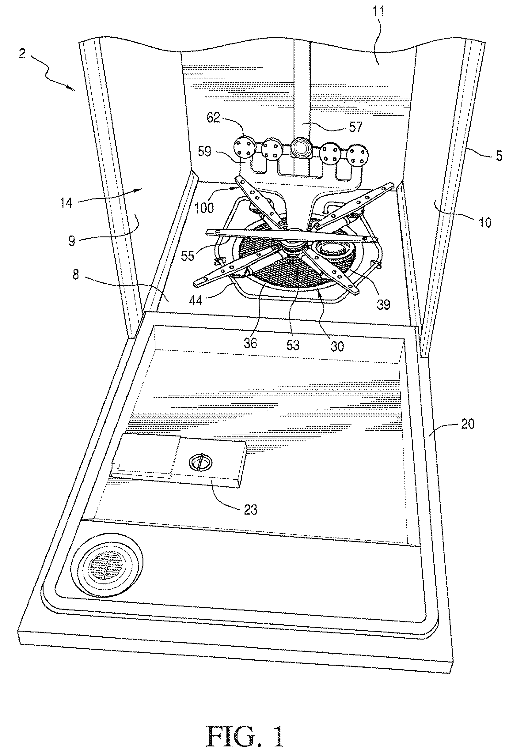
[0016]With initial reference to FIGS. 1 and 2, a dishwasher constructed in accordance with the present invention as generally indicated at 2. As shown, dishwasher 2 includes a tub 5 which is preferably molded of plastic so as to include integral bottom, side, and rear walls 8-11 respectively, as well as a top wall (not shown). Tub 5 defines a washing chamber 14 within which soiled kitchenware is adapted to be placed upon shiftable upper and lower racks (not shown for drawing clarity), with the kitchenware being cleaned during a washing operation. Tub 5 has attached thereto a pivotally supported door 20 used to seal chamber 14 during the washing operation. In connection with the washing operation, door 20 is preferably provided with a detergent tray assembly 23 within which a consumer can place liquid or particulate washing detergent for dispensing at predetermined portions of the washing operation. Of course, dispensing detergent in this fashion is known in the art such that this ar...


PUM


Abstract

A sequencing diverter valve system in a washing appliance includes a fluid distribution manifold having a fluid inlet for receiving washing fluid and a plurality of fluid outlets. A fluid responsive rotating drive arm is connected to a drive reduction mechanism which, in turn, is operatively connected to a rotating sequencing valve for shifting the valve through a plurality of discrete positions at a rate of rotation less than the rate of rotation of the drive arm. As it rotates, the sequencing valve sequentially directs the washing fluid to a respective one or more of the plurality of fluid outlets.

Description

BACKGROUND OF THE INVENTION[0001]1. Field of the Invention[0002]The present invention pertains to the art of valve systems for appliances and, more specifically, to a diverter valve system for selectively supplying washing fluid in an appliance.[0003]2. Description of the Related Art[0004]Washing appliances, particularly dishwashers, are provided with internal spraying devices for directing streams of washing liquid at objects to be washed. More specifically, a dishwasher includes a washing chamber having a bottom sump in fluid communication with a motor driven pump to supply washing liquid under pressure to a spraying device that directs streams of washing liquid at dishes held in the washing chamber. As is known, the streams of washing liquid generally flow from one or more rotatable wash arms due to the effect of reactions caused by fluid jets coming out of respective pressure nozzles. It is also known to provide a dishwasher with fixed spray nozzle units.[0005]Typically, the num...

Claims


Application Information

Patent Timeline
Patent Type & Authority Patents(United States)
IPC IPC(8): B08B3/02
CPCA47L15/23A47L15/4221
Inventor BERTSCH, ROGER JAMESGILLUM, BRUCE W.WILSON, DONALD JOSEPH
Owner WHIRLPOOL CORP
Learn More