Bistable hammer for a chronograph mechanism

a technology of chronograph mechanism and hammer, which is applied in the direction of shock protection arrangement, instruments, and horology, can solve the problem of complex implementation of system types

Active Publication Date: 2011-04-05
OMEGA SA
View PDF9 Cites 6 Cited by
  • Summary
  • Abstract
  • Description
  • Claims
  • Application Information

AI Technical Summary

Benefits of technology

[0006]It is an object of the present invention to overcome all or part of the aforementioned drawbacks by proposing a less complex chronograph mechanism, which is activated more directly by the push-buttons and whose hammer thus operates more reliably.
[0014]the hammer lever includes a pin that enters into contact with a different surface of the jumper spring for each position of the hammer, so as to make the positions of said hammer stable, via a single jumper spring;
[0015]at least one of the surfaces of the jumper spring includes a notch for receiving the lever pin, so as to improve the stability of cooperation between the lever and said jumper spring;

Problems solved by technology

This type of system is complex to implement and requires the push-buttons to be very indirectly linked to the member to be controlled.

Method used


Image

  • Bistable hammer for a chronograph mechanism
  • Bistable hammer for a chronograph mechanism
  • Bistable hammer for a chronograph mechanism

Examples


Embodiment Construction

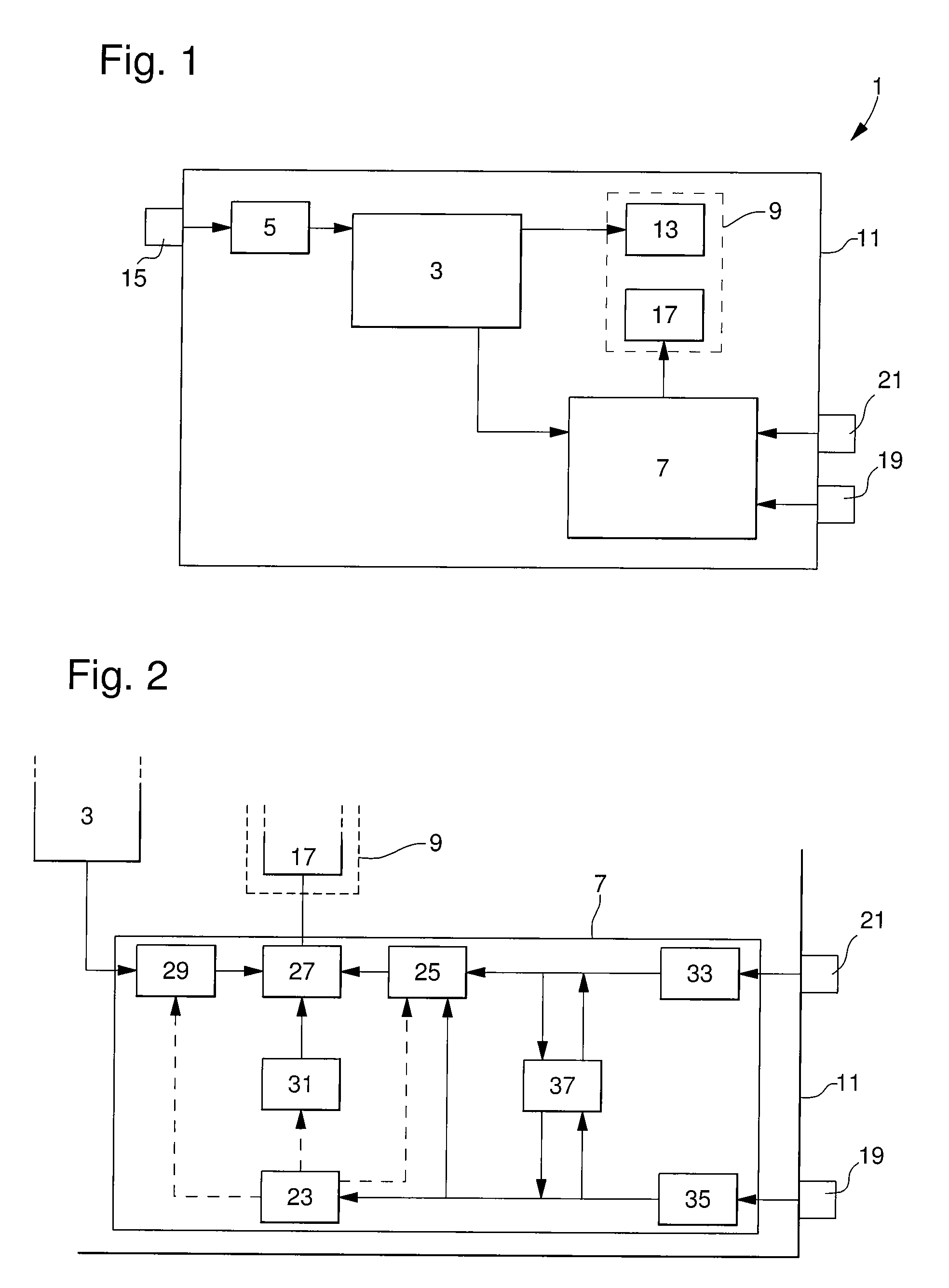
[0031]As illustrated in FIG. 1, the invention concerns a timepiece 1, whose case 11 includes a timepiece movement 3, a time-setting system 5, a chronograph mechanism 7 and a display system 9.

[0032]Timepiece movement 3, which is preferably mechanical, moves an indicator device 13 of display system 9, which may, for example, include a dial with an hour index and hands, which move above the dial and are connected to timepiece movement 3. The movement can be set via time-setting system 5, for example by operating a crown 15, which projects from case 11. As timepiece movement 3 is not protected by the invention, it will not be explained further here.

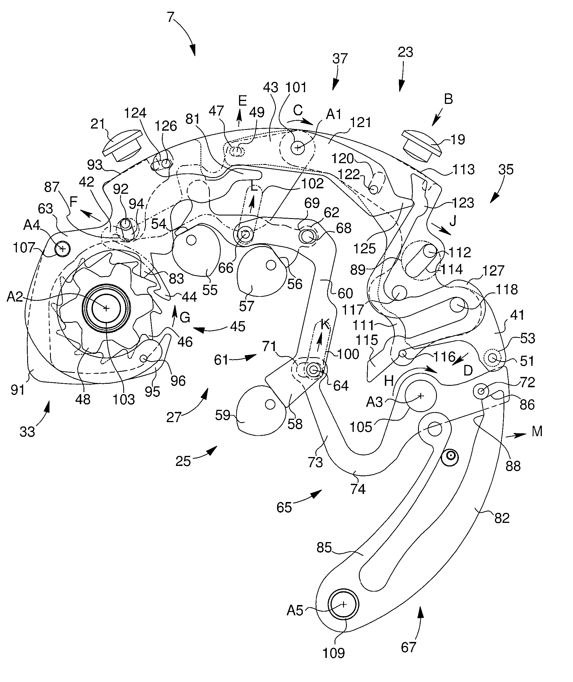
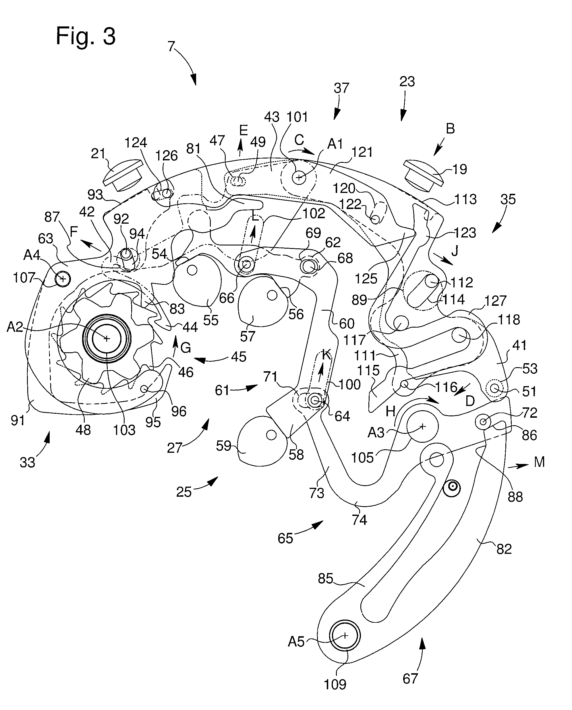
[0033]Two stage chronograph mechanism 7 moves a second indicator device 17, including at least one counter belonging to display system 9. Chronograph mechanism 7 is controlled by two control members 19, 21 and includes, as can be seen in FIG. 2, a control system 23, a reset device 25, a gear train device 27, a coupling device 29, an immobilis...


PUM


Abstract

The invention relates to a chronographic timepiece and a chronograph mechanism (7) thereof including an elapsed time indicator member (17), a reset control member (21), and a reset device (25) for the indicator member, which includes a hammer (61), mounted in translation between an inactive position, where the hammer (61) is moved away from heart-pieces (55, 57, 59) that are connected to the indicator member (17), and an active position where stop members (54, 56, 58) of the hammer exert a reset force against the heart-pieces. The hammer (61) includes two studs (64, 66) mounted so as to slide in holes (100, 102) such that the movement vectors (L, K) of the studs (64, 66) between the positions are collinear and not aligned.

Description

[0001]This application claims priority from European Patent Application No. 07150324.7 filed Dec. 21, 2007, the entire disclosure of which is incorporated herein by reference.FIELD OF THE INVENTION[0002]The invention relates to a bistable hammer for a chronograph mechanism.[0003]It applies, in particular, to “two stage” chronographs, which have two push-buttons, in this case a first push-button, which starts and stops the chronograph mechanism and a second push-button, which controls the reset function.BACKGROUND OF THE INVENTION[0004]It is known to mount a chronograph mechanism hammer in an elastic manner, i.e. so that at the moment when the indicator device is activated by a first push-button, the hammer is mechanically brought into a clicked position. A second push-button activates the reset function, which then moves the click, enabling the hammer to be repositioned against the heart-pieces of the mechanism, by elastic let down.[0005]This type of system is complex to implement a...

Claims


Application Information

Patent Timeline
Patent Type & Authority Patents(United States)
IPC IPC(8): G04F7/08
CPCG04F7/08G04F7/0804G04F7/0819G04F7/0847G04B43/002G04F7/00G04B19/00
Inventor WYSSBROD, BAPTIST
Owner OMEGA SA
Why Eureka
Try Eureka