High efficiency generator

a generator and high-efficiency technology, applied in the direction of power conversion systems, electric generator control, dynamo-electric converter control, etc., can solve the problems of adding significant cost and/or mass to the generator, the amount of power used to conduct the diodes may provide a power loss at 100 amps of about 180 watts, and the total diode voltage loss of about 1.8 volts

Inactive Publication Date: 2011-04-05
GM GLOBAL TECH OPERATIONS LLC
View PDF11 Cites 12 Cited by
  • Summary
  • Abstract
  • Description
  • Claims
  • Application Information

AI Technical Summary

Problems solved by technology

High efficiency generators usually employ shaped conductor stator windings to reduce copper losses, thinner stator laminations to reduce iron losses, low friction bearings, a laminated rotor construction and permanent magnetic excitation, all of which add significant cost and / or mass to the generator.
Particularly, the amount of power used to conduct the diodes may provide a power loss at 100 amps of about 180 watts and a total diode voltage loss of about 1.8 volts.

Method used


Image

  • High efficiency generator
  • High efficiency generator
  • High efficiency generator

Examples


Embodiment Construction

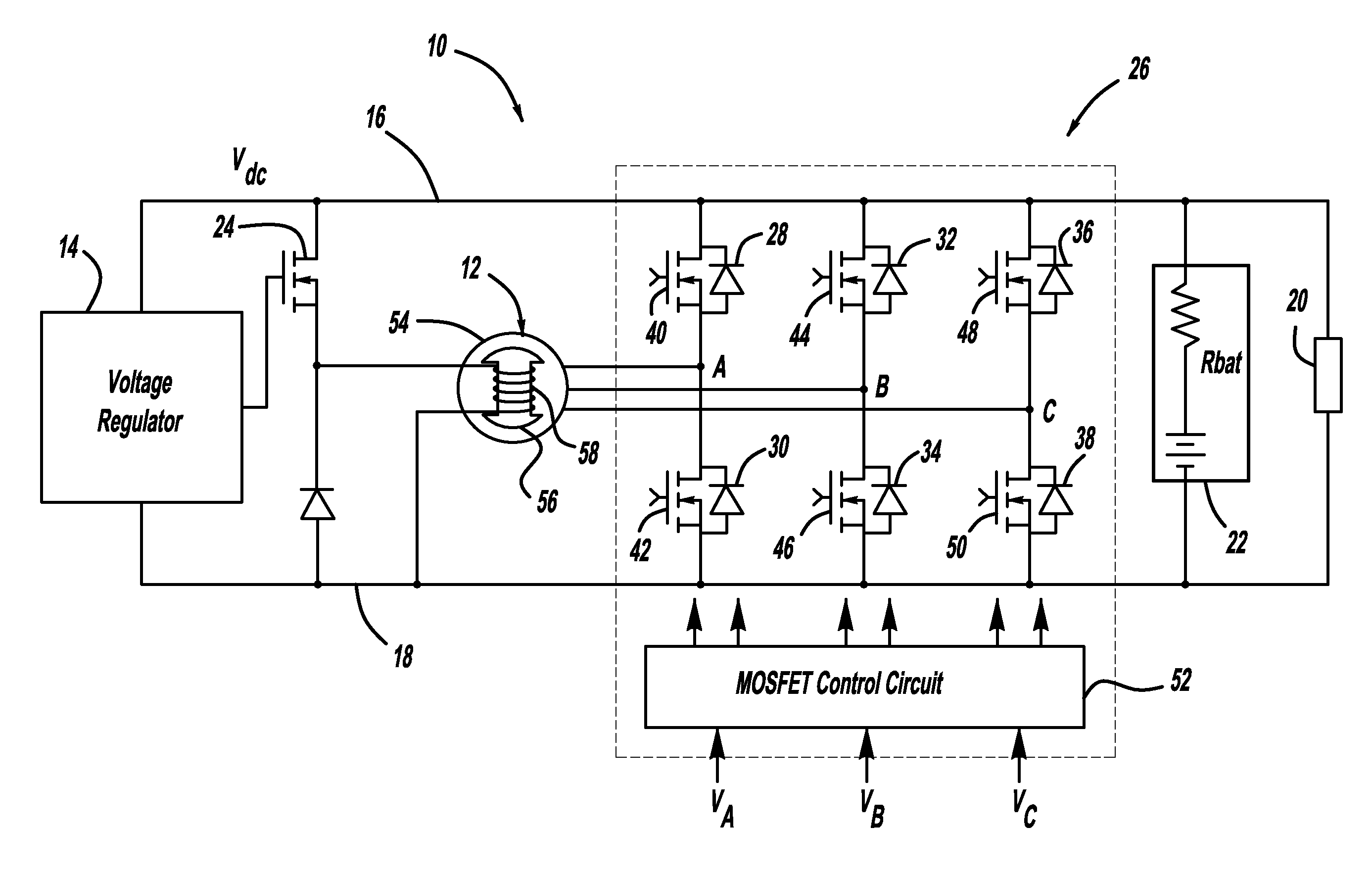
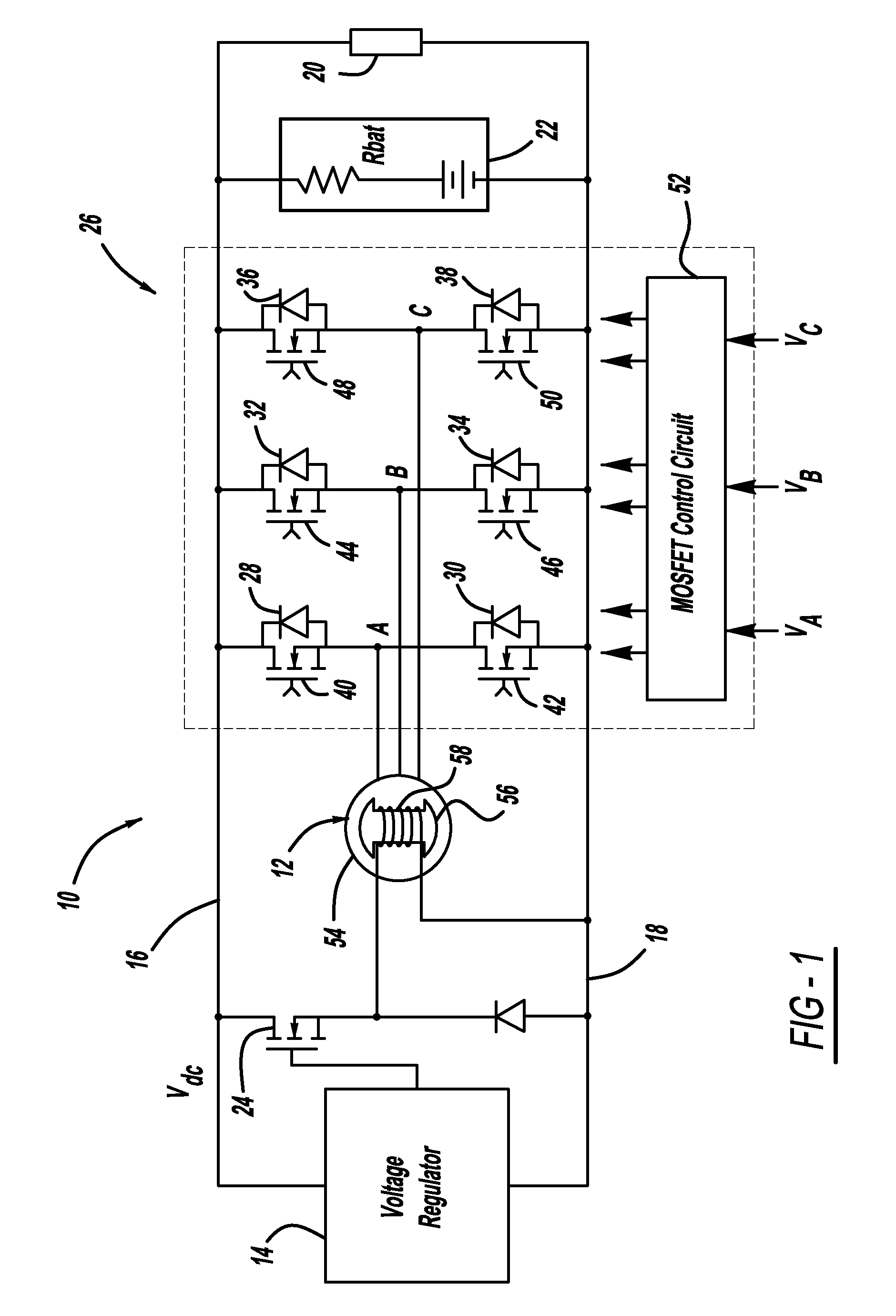
[0013]The following discussion of the embodiments of the invention directed to a generator system employing an active rectifier bridge including MOSFET switches is merely exemplary in nature, and is in no way intended to limit the invention or its applications or uses.

[0014]FIG. 1 is a schematic diagram of a generator system 10, according to an embodiment of the present invention. The system 10 includes a three-phase wound rotor synchronous machine 12, such as claw-pole machine, having a field coil 58 in a rotor 56 of the machine 12 and three-phase AC synchronous armature coils in a stator 54 of the machine 12. In this non-limiting embodiment, the machine 12 is a Lundell machine. Permanent magnets can be incorporated in the rotor 56 of the machine 12 between the claw-poles to provide additional flux to that produced by the field coil 58, where the total flux is responsible to produce voltage in the armature coils.

[0015]The system 10 also includes a voltage regulator 14 that regulate...


PUM


Abstract

A generator system that includes a three-phase AC machine and an active rectifier bridge employing low on-resistance MOSFET switches for converting the AC current from the machine to a DC current. The system also includes a switch control circuit to switch the MOSFET switches in synchronization with the three-phase current flow. The system determines the phase-to-ground voltages of the machine as inputs to the switch control circuit. The control circuit calculates the phase-to-phase voltages from the phase-to-ground voltages. The control circuit then determines if each of the phase-to-phase voltages is above or below first and second predetermined threshold voltages, where if the phase-to-phase voltage is above the first threshold voltage, the control circuit closes the switch, and if the phase-to-phase voltage is below the second threshold voltage, the control circuit opens the switch.

Description

CROSS-REFERENCE TO RELATED APPLICATIONS[0001]This application claims the benefit of the filing date of U.S. Provisional Application No. 60 / 938,573, filed May 17, 2007, titled High Efficiency Generator.BACKGROUND OF THE INVENTION[0002]1. Field of the Invention[0003]This invention relates generally to a generator system and, more particularly, to a generator system for a vehicle that includes an active rectifier bridge employing low on-resistance metal oxide semiconductor field effect transistor (MOSFET) switches and a control scheme for controlling the switches.[0004]2. Discussion of the Related Art[0005]Vehicles employ generators that are driven by a belt coupled to the vehicle engine to generate electrical power. Automotive electrical generators typically employ an AC synchronous machine with three-phase stator windings, a DC excitation winding on a claw-pole rotor, a voltage regulator and a three-phase diode bridge rectifier to produce a DC output. The excitation current of the sy...

Claims


Application Information

Patent Timeline
Patent Type & Authority Patents(United States)
IPC IPC(8): H02P9/30
CPCH02M7/219H02P9/30
Inventor NAMUDURI, CHANDRA S.HAO, LEI
Owner GM GLOBAL TECH OPERATIONS LLC
Why Eureka
Try Eureka