Dimmer circuit for LED

a technology of led light and circuit, which is applied in the direction of electric variable regulation, process and machine control, instruments, etc., can solve the problems of not being able to adapt easily, the heat generation of the circuit is relatively high, and the led does not provide the minimum load necessary.

Inactive Publication Date: 2006-09-05
LEDTRONICS
View PDF2 Cites 237 Cited by
  • Summary
  • Abstract
  • Description
  • Claims
  • Application Information

AI Technical Summary

Benefits of technology

[0007]The present invention provides a circuit that supplies a specialized load to a conventional AC dimmer which, in turn, controls a LED device. The circuit draws limited power from the energy source and also operates in a manner such that the heat generated by the circuit is substantially reduced.

Problems solved by technology

The illumination output from LEDs typically have a single intensity and are not easily adapted to having multiple levels of intensity and thus to dimming.
Specifically, LEDs do not provide the minimum load necessary when used with conventional dimmers.
Those LED circuits with dimmer devices draw higher power from the AC input source which, in turn, generates relatively higher heat levels which is undesirable in LED based circuits.

Method used


Image

  • Dimmer circuit for LED
  • Dimmer circuit for LED
  • Dimmer circuit for LED

Examples


Embodiment Construction

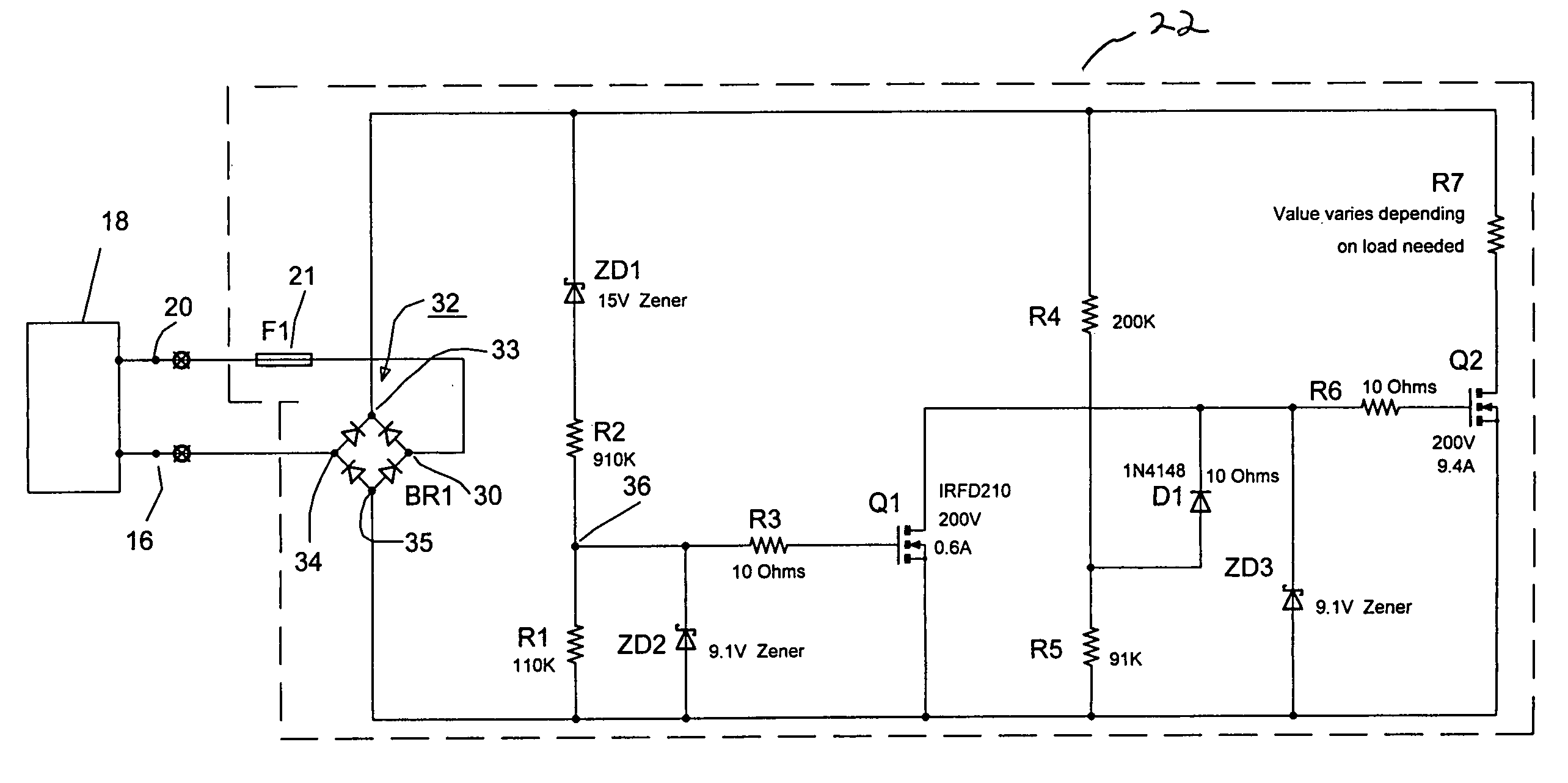
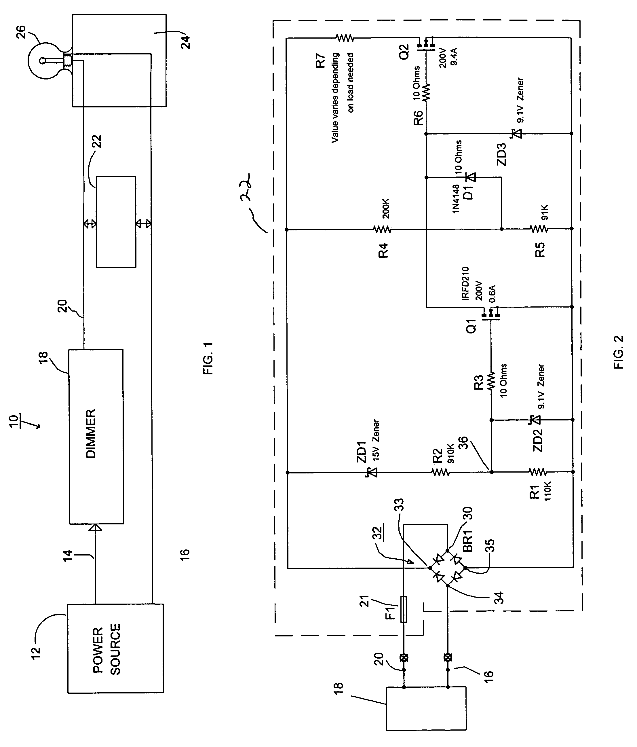
[0013]Referring to FIG. 1, a block diagram of the system 10 in which the circuit 22 of the present invention is utilized is illustrated.

[0014]The AC home power source 12 provides output leads 14 (the “hot” lead) and 16 (“neutral”), lead 14 being coupled to a conventional dimmer 18. The output lead 20 from dimmer 18, corresponding to hot lead 14 is coupled to a first input of circuit 22 of the present invention, neutral lead 16 being coupled to a second input of circuit 22. In the embodiment illustrated, the output of circuit 22 is coupled to Edison base socket 24 having a LED bulb 26 inserted therein. Although only a single LED bulb 26 is shown, a plurality of such LED bulbs can be placed in parallel across circuit 22. In an alternate arrangement, circuit 22 can be combined with an Edison base and the resulting combination then inserted into a conventional socket, thus eliminating the necessity of a separate wiring connection for circuit 22.

[0015]As will be set forth hereinafter in ...


PUM


Abstract

The AC output from a source is rectified and applied to a resistor / Zener diode circuit connection which determines the magnitude of the rectified voltage applied via a circuit to a first MOSFET device. The inverted output of the first MOSFET device is applied to the gate electrode of a second MOSFET device in a manner such that the second MOSFET device is ON even when the AC output passes through zero. The output of the second MOSFET device is connected to a resistor which determines the magnitude of the load applied to the dimmer.

Description

BACKGROUND OF THE INVENTION[0001]1. Field of the Invention[0002]The present invention provides a simplified and inexpensive circuit for dimming light emitting diodes utilizing a conventional TRIAC AC dimmer.[0003]2. Background of the Invention[0004]Circuits for dimming incandescent bulbs have been available in the prior art. For example, U.S. Pat. No. 6,566,819 to Wolff discloses a light control / dimmer system that can be touch operated and includes a programmable timer that controls the light attached thereto by switching the device to an “OFF” position after a predetermined time period. In most dimmers, the current will not go to zero unless there is a minimum load provided by the device being dimmed. Thus, the dimmer device typically has a minimum load placed on it of approximately 5 watts.[0005]Light emitting diodes (“LEDs”) that provide a specific, focused light output of a predetermined wavelength have been available for a number of years. U.S. Pat. No. 6,598,996 to Lodhie sets...

Claims


Application Information

Patent Timeline
Patent Type & Authority Patents(United States)
IPC IPC(8): H02M5/00
CPCH05B33/0815H05B39/044Y10S323/905H05B45/31Y02B20/00
Inventor BROWN, EMERY ALANLODHIE, PERVAIZ
Owner LEDTRONICS
Why Eureka
Try Eureka