System, device, and method for embedded S-parameter measurement

a technology of embedded test methods and measurement methods, applied in the field of electronic circuit testing, can solve the problems of complex calibration procedures, inability to effectively and efficiently determine s-parameters, and inability to achieve high accuracy, wide dynamic range, and high accuracy

Inactive Publication Date: 2011-04-12
UNIV OF FLORIDA RES FOUNDATION INC
View PDF12 Cites 6 Cited by
  • Summary
  • Abstract
  • Description
  • Claims
  • Application Information

AI Technical Summary

Benefits of technology

[0009]The present invention provides a system, device, and related methods for effectively and efficiently determining s-parameters. More particularly, the present invention provides for a system, device, and related methods for embedded s-parameter determinations or measurements associated with a high-frequency IC or other circuit. The embedded s-parameter determinations obtained with the present invention can have high precision and can encompass a wide dynamic range. The embedded device of the present invention, moreover, can obviate the need for cables and connectors, and thus can be implemented using relatively small amounts of the “real estate” available on a typical semiconductor chip. The system, device, and methods of the present invention effect significant savings in terms of cost and time in comparison to conventional systems, devices, and techniques.

Problems solved by technology

The s-parameters are typically used to characterize high-frequency networks, especially because simpler models that are valid at lower frequencies are usually inadequate in the case of high-frequency networks.
Without an effective and efficient on-chip embedded test technique, complex calibration procedures are typically required in order to factor out the effect of unwanted parasitic circuit elements.
So, too, without an effective and efficient on-chip embedded test technique, test equipment with high precision as well as a wide dynamic range—and, accordingly, involving significant costs—is needed to measure RF / microwave performance and attain a proper calibration.

Method used


Image

  • System, device, and method for embedded S-parameter measurement
  • System, device, and method for embedded S-parameter measurement
  • System, device, and method for embedded S-parameter measurement

Examples


Embodiment Construction

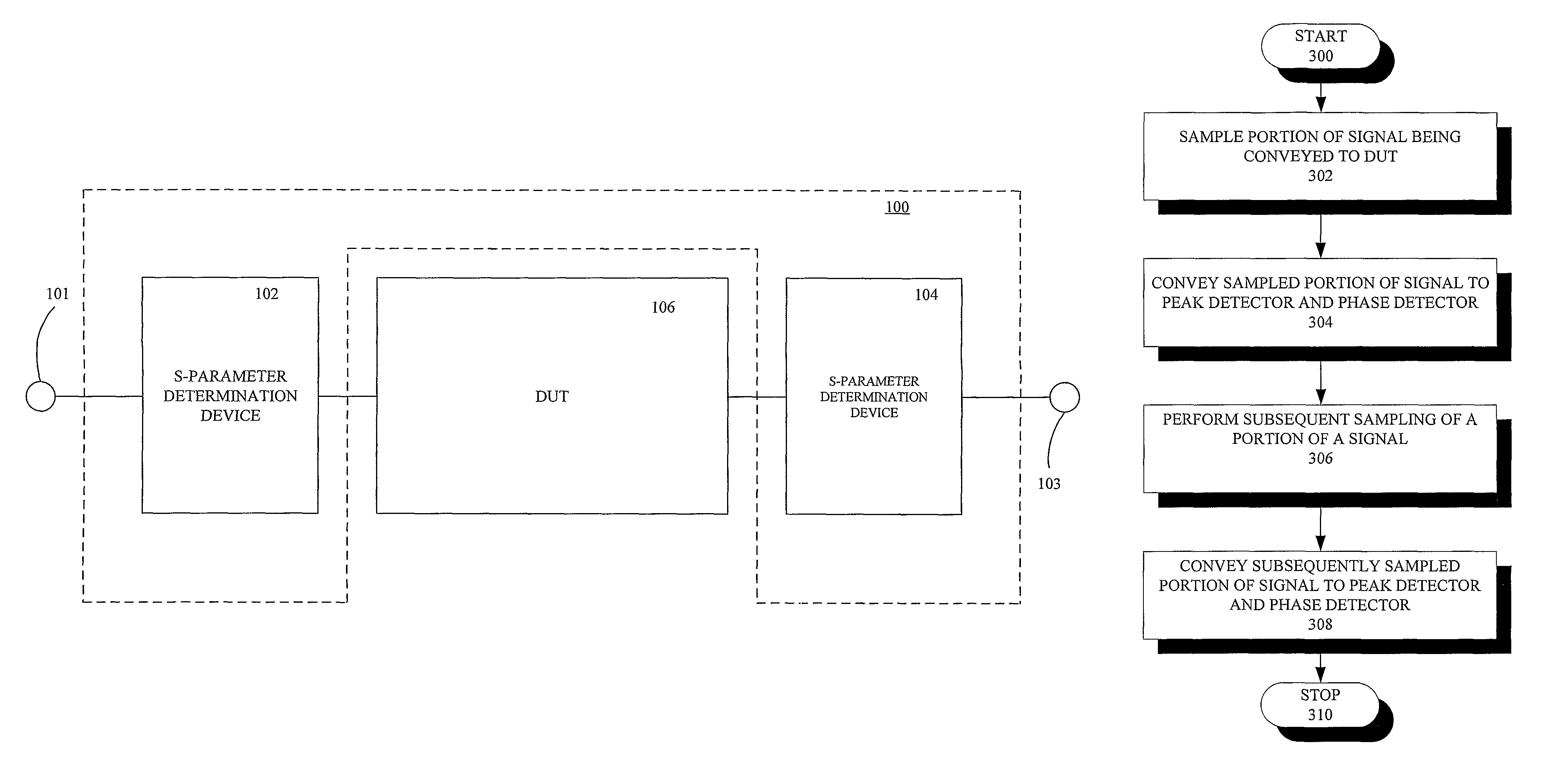
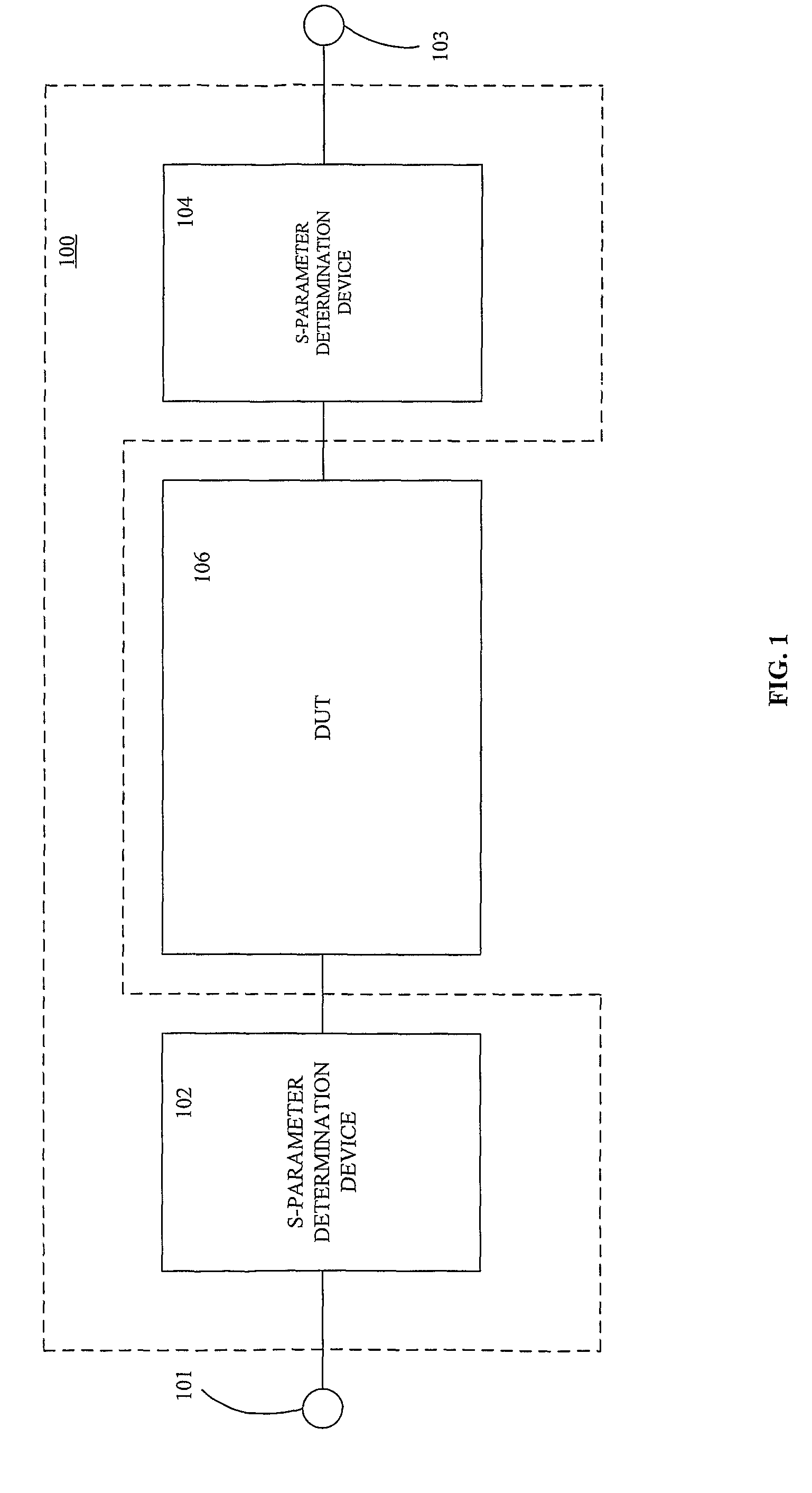
[0027]FIG. 1 is a schematic diagram of a system 100 for obtaining an s-parameter measurement, according to one embodiment of the invention. As illustrated, the system 100 includes a first device 102 defining a first s-parameter test circuit along with a second device 104 defining a second s-parameter test circuit. Each device 102, 104 illustratively connects electrically to a different port of a device-under-test (DUT) 106. The exemplary DUT 106 illustratively comprises a two-port device. It will be apparent from the ensuing discussion, however, that the system 100 can be expanded to connect to additional ports of a DUT having more than two ports. Although the structure and functionality of the system 100 are described herein in the context of an exemplary two-port DUT, this is merely for ease of understanding without any loss of generality; the structure and functionality of an alternative embodiment in which the system 100 operates with a DUT having more than two ports will be cle...


PUM


Abstract

An embedded s-parameter measurement system for measuring or determining an s-parameter is provided. The system includes an s-parameter test circuit for connecting to a port of a high-frequency multi-port device-under-test (DUT). The s-parameter test circuit includes a directional coupler for sampling a forward signal conveyed to the DUT and for sampling a reverse signal reflected by the DUT. The s-parameter test circuit also includes a peak detector electrically connected to the directional coupler for detecting a magnitude of a signal conveyed to the peak detector by the directional coupler. The s-parameter test circuit further includes a phase detector electrically connected to the directional coupler for determining a phase of a signal conveyed to the phase detector by the directional coupler, and at least one other s-parameter test circuit for connecting to another port of the high-frequency multi-port DUT.

Description

CROSS-REFERENCE TO RELATED APPLICATIONS[0001]This application is a §371 national stage entry of International Application No. PCT / US2006 / 029048, filed Jul. 25, 2006, which claims the benefit of U.S. Provisional Application No. 60 / 702,126, filed Jul. 25, 2005, both of which are hereby incorporated by reference.[0002]The subject invention was made with government support under Grant No. 0325340 awarded by the National Science Foundation. The government has certain rights in the invention.FIELD OF THE INVENTION[0003]The present invention is related to the field of electronic circuits, and, more particularly, to the testing of electronic circuits.BACKGROUND[0004]The performance of a microwave or other high-frequency integrated circuit (IC) can be verified using various testing techniques. In most instances, however, the preferred technique is to obtain measurements with a vector network analyzer. A vector network analyzer yields the complex impedance of an IC or other circuit at a given...

Claims


Application Information

Patent Timeline
Patent Type & Authority Patents(United States)
IPC IPC(8): G01R27/02G01R27/32
CPCG01R31/2884G01R27/28
Inventor EISENSTADT, WILLIAM R.FOX, ROBERT M.YOON, JANG SUP
Owner UNIV OF FLORIDA RES FOUNDATION INC
Why Eureka
Try Eureka