Battery fuse assembly

a fuse assembly and battery technology, applied in the direction of basic electric elements, electrical equipment, emergency protective devices, etc., can solve the problems of component damage, component damage, component damage, etc., and achieve the effect of preventing current flow

Active Publication Date: 2011-04-12
EATON INTELLIGENT POWER LTD
View PDF23 Cites 26 Cited by
  • Summary
  • Abstract
  • Description
  • Claims
  • Application Information

AI Technical Summary

Benefits of technology

[0009]The invention provides a battery fuse assembly with an improved means for preventing electrical circumvention of a fuse. The fuse includes a housing configured to protect a fusible element of the fuse from exposure to ambient particles. By shielding the fusible element from ambient particles, the housing protects the fusible element from degradation due to rust, corrosion, etc. Thus, the fuse can safely and reliably be used in marine (and other) applications. The housing also contains fuse element particles within the housing under fault loads.
[0010]In one aspect of the invention, the fuse includes a housing having a body member and a fusible element encased therein. For example, the housing can have a substantially cubical shape. The fusible element includes a fault element configured to melt, disintegrate, fail, or otherwise open to break an electrical circuit that will be coupled to the fuse, in response to an over-current in the circuit. The housing includes a heat-resistant plastic or another heat-resistant material, such as Polyphenylene Sulfide, configured to contain an arc generated by the fault element in response to the over-current in the circuit. The material is configured to prevent the arc from mixing with ambient particles, thereby making the fuse ignition protected.
[0011]The housing also is configured to shield the fusible element from ambient particles, thereby increasing the expected long-term performance of the fusible element. For example, by shielding the fusible element from water and other ambient particles, the housing can protect the fusible element from degradation due to rust, corrosion, etc.
[0012]The body member includes an insulating material, such as a ceramic. The insulating material is configured to interrupt the arc generated by the fault element in response to the over-current. The body member includes an upper surface, a lower surface, and a side surface. The fusible element is substantially disposed about the side surface and includes an upper portion that engages at least a portion of the upper surface, a lower portion that engages at least a portion of the lower surface, and the fault element that engages the side surface of the body member. In certain exemplary embodiments, a surface of the fault element can include a layer of electrically non-conductive plastic, such as Silicone. Tests have shown that application of such a plastic layer can prevent long arcing duration, which is otherwise common during a high voltage over-current.
[0015]The lower portion of the mounting plate body includes a terminal bore configured to receive a terminal post of a battery. A threaded mounting stud extends through the upper portion of the mounting plate body, in a direction substantially perpendicular to the upper portion. The mounting stud is configured to receive a fuse and a power supply cable in an electrical circuit. The body of the mounting plate is configured to transmit current from the terminal post to the mounting stud for transmission to the fuse and the power supply cable. In certain exemplary embodiments, the second member is configured to act as an anti-rotation stop for preventing movement of the fuse relative to the upper portion of the body of the mounting plate.
[0017]The insulating material is configured to electrically isolate the fuse and the power supply cable from the mounting stud, and is intended to prevent current flow from the mounting stud to the power supply cable from circumventing the fuse, without the need for an insulating nut.

Problems solved by technology

Known arrangements of these types may be susceptible to undesirable shorting or bypassing of the current path through the fuse if the ring terminal is inadvertently brought into contact with the terminal post or mounting stud, creating a direct current path from the terminal post or mounting stud to the ring terminal, without first passing through the fuse.
Thus, despite the presence of the fuse in the circuit, component damage may result.
The standard nut will not prevent current from circumventing the fuse and thereby causing component damage.
Such deposits can significantly degrade the performance of the fault element 20a.

Method used


Image

  • Battery fuse assembly
  • Battery fuse assembly
  • Battery fuse assembly

Examples


Embodiment Construction

[0029]The following description of exemplary embodiments refers to the attached drawings, in which like numerals indicate like elements throughout the several figures.

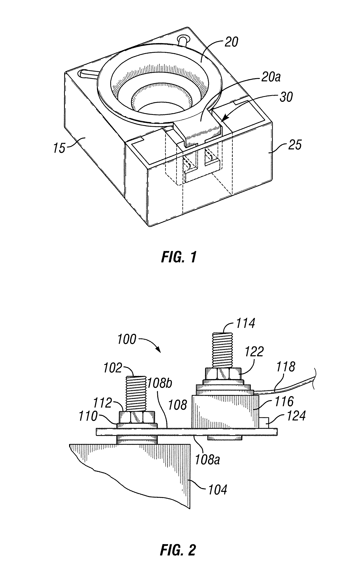
[0030]FIG. 2 is an elevational view of a battery fuse assembly 100 coupled to a terminal post 102 of a battery 104, in accordance with certain exemplary embodiments. The battery 104 is a storage battery configured to power one or more electrical circuits and / or components of a vehicle, such as an automobile or boat. As the construction and operation of such a battery 104 is readily appreciated by a person skilled in the art, further discussion thereof is omitted. For example, the terminal post 102 can include a positive or negative terminal of the battery 104.

[0031]A conductive mounting plate 108 (i.e., a bus bar) of the battery fuse assembly 100 is attached to the terminal post 102 via a fastener, such as a washer 110 and nut 112 with threaded engagement. The mounting plate 108 includes an elongated body 108a that ext...


PUM


Abstract

A fuse includes a fusible element and a body member encased within a heat-resistant housing. The fusible element is configured to open an electrical circuit coupled to a storage battery in response to an over-current in the electrical circuit. The housing is configured to contain an arc generated by the fusible element in response to the over-current and to shield the arc and the fusible element from ambient particles. Thus, the fuse is ignition protected. The body member includes an insulating material configured to interrupt the arc. The housing includes an opening configured to receive a terminal of the storage battery or a terminal of a mounting plate. An insulating material disposed about a first end of the mounting plate terminal is configured to electrically isolate the fuse and a power supply cable in the electrical circuit from the mounting plate terminal.

Description

TECHNICAL FIELD[0001]The invention relates generally to fuse assemblies, and more particularly, to fuse assemblies for storage batteries.BACKGROUND OF THE INVENTION[0002]Fuses are widely used as over-current protection devices for preventing damage to electrical circuits. Fuses include fuse terminations configured to form an electrical connection between an electrical power source and an electrical component or a combination of electrical components or loads arranged in an electrical circuit. Fuses also include one or more fusible links or elements disposed between the fuse terminations. When electrical current through a fuse exceeds a predetermined limit, the fusible elements melt, disintegrate, fail, or otherwise open to break an electrical and open the electrical circuit associated with the fuse, thereby preventing damage to the electrical components in the circuit.[0003]In vehicle electrical systems, storage batteries or power sources such as alternators are used to power electr...

Claims


Application Information

Patent Timeline
Patent Type & Authority Patents(United States)
IPC IPC(8): H01H85/175H01H85/08
CPCH01H85/044H01H85/003H01H2085/383H01H85/38H01H2085/025H01H85/17Y02E60/10
Inventor RAHMAN, NAEEMCZYZ, ANTHONYHA, CUONG
Owner EATON INTELLIGENT POWER LTD
Why Eureka
Try Eureka