Scatter attenuation tomography

a tomography and scattering technology, applied in the direction of material analysis using wave/particle radiation, instruments, nuclear engineering, etc., can solve the problems of large and achieve the effect of reducing the size and cost of x-ray ct systems

Inactive Publication Date: 2011-04-12
AMERICAN SCI & ENG INC
View PDF47 Cites 30 Cited by
  • Summary
  • Abstract
  • Description
  • Claims
  • Application Information

AI Technical Summary

Problems solved by technology

Disadvantages of x-Ray CT systems include their size and cost.
Both the size and cost arise largely because of the rapidly rotating gantries on which the x-ray source and detector arrays are mounted.

Method used


Image

  • Scatter attenuation tomography
  • Scatter attenuation tomography
  • Scatter attenuation tomography

Examples


Embodiment Construction

[0036]The current invention builds upon the teachings of U.S. Pat. No. 5,930,326 by describing a simple and elegant method for determining a much more accurate measurement of the density of concealed organic objects. In accordance with preferred embodiments of the present invention, the side-scatter distribution is detected in two detector arrays. The method allows for a full three-dimensional reconstruction of the organic contents of the container, along with the more accurate density determination than could be obtained using the methods taught in U.S. Pat. No. 5,930,326.

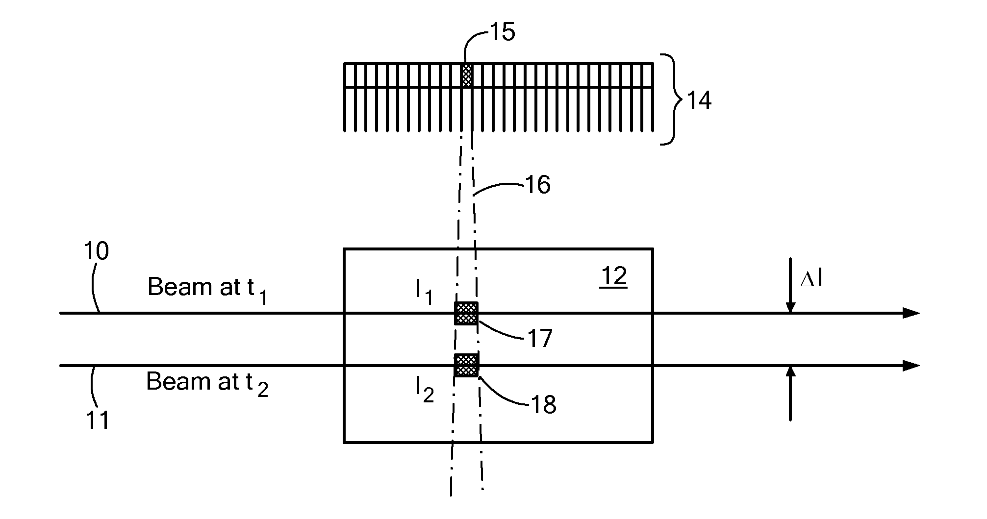
[0037]As now described with reference to FIG. 1, a novel technique referred to herein as Scatter Attenuation Tomography (SAT), generally, looks at the fall-off, in the scattered radiation, from a raster-scanning x-ray beam as the beam moves deeper into an object of interest.

[0038]It is to be noted that while the present description refers to an incident beam 10 of penetrating radiation as an x-ray beam, it is to b...


PUM

PropertyMeasurementUnit
densityaaaaaaaaaa
densityaaaaaaaaaa
energyaaaaaaaaaa

Abstract

A system and methods for characterizing an inspected object on the basis of attenuation determined from pair-wise illuminated voxels. A beam of penetrating radiation characterized by a propagation direction and an energy distribution is scanned relative to an object, while scatter detectors with collimated fields-of-view detect radiation scattered by each voxel of the inspected object that is intercepted by the incident beam of penetrating radiation. By calculating the attenuation of penetrating radiation between pairs of voxels illuminated sequentially by the incident beam, a tomographic image is obtained characterizing the three-dimensional distribution of attenuation in the object of one or more energies of penetrating radiation, and thus of various material characteristics.

Description

[0001]The present application is a continuation-in-part of U.S. patent application Ser. No. 12 / 489,620, filed Jun. 23, 2009, which is a continuation of U.S. Ser. No. 11 / 843,185, which issued on Jun. 23, 2009 as U.S. Pat. No. 7,551,718. Like the two foregoing applications, the present application claims priority from U.S. Provisional Patent Application, Ser. No. 60 / 823,328, filed Aug. 23, 2006. All of the foregoing prior applications are incorporated herein by reference.TECHNICAL FIELD[0002]The present invention relates to methods and systems for inspecting objects by means of penetrating radiation, and more particularly, to inspection of objects by simultaneous detection of penetrating radiation scattered into distinct, and possibly opposing, directions.BACKGROUND OF THE INVENTION[0003]In the period since September, 2001, X-Ray Computerized Tomography (CT) has been used extensively to search for explosive materials concealed in airline baggage. The method works by measuring the “CT ...

Claims


Application Information

Patent Timeline
Patent Type & Authority Patents(United States)
IPC IPC(8): G01N23/201
CPCG01V5/0041G01V5/0025
Inventor ROTHSCHILD, PETER J.
Owner AMERICAN SCI & ENG INC
Why Eureka
Try Eureka