Flexible shaft for gas turbine engine

a gas turbine engine and flexible technology, applied in the direction of couplings, liquid fuel engines, gearing, etc., can solve the problems of axial misalignment and shift, easy to breakage and wear,

Active Publication Date: 2011-04-19
RTX CORP
View PDF18 Cites 358 Cited by
  • Summary
  • Abstract
  • Description
  • Claims
  • Application Information

AI Technical Summary

Problems solved by technology

During operation, forces and torque transferred through the epicyclic gear train can create tremendous stresses within the gear train components, making them susceptible to breakage and wear, even under ideal conditions.
Such axial misalignments and shifts can be induced by imbalances in rotating hardware, manufacturing imperfections, and transient flexures of the shafts and support frames due to aircraft maneuvers.

Method used


Image

  • Flexible shaft for gas turbine engine
  • Flexible shaft for gas turbine engine
  • Flexible shaft for gas turbine engine

Examples


Embodiment Construction

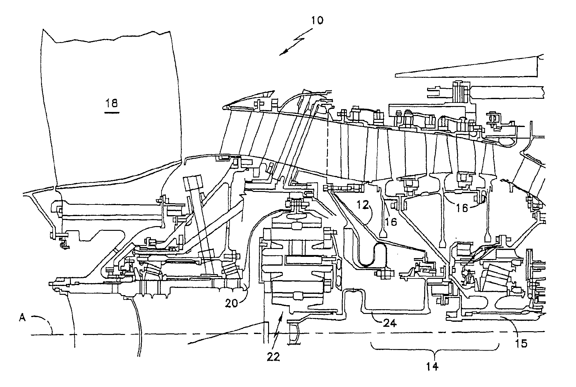
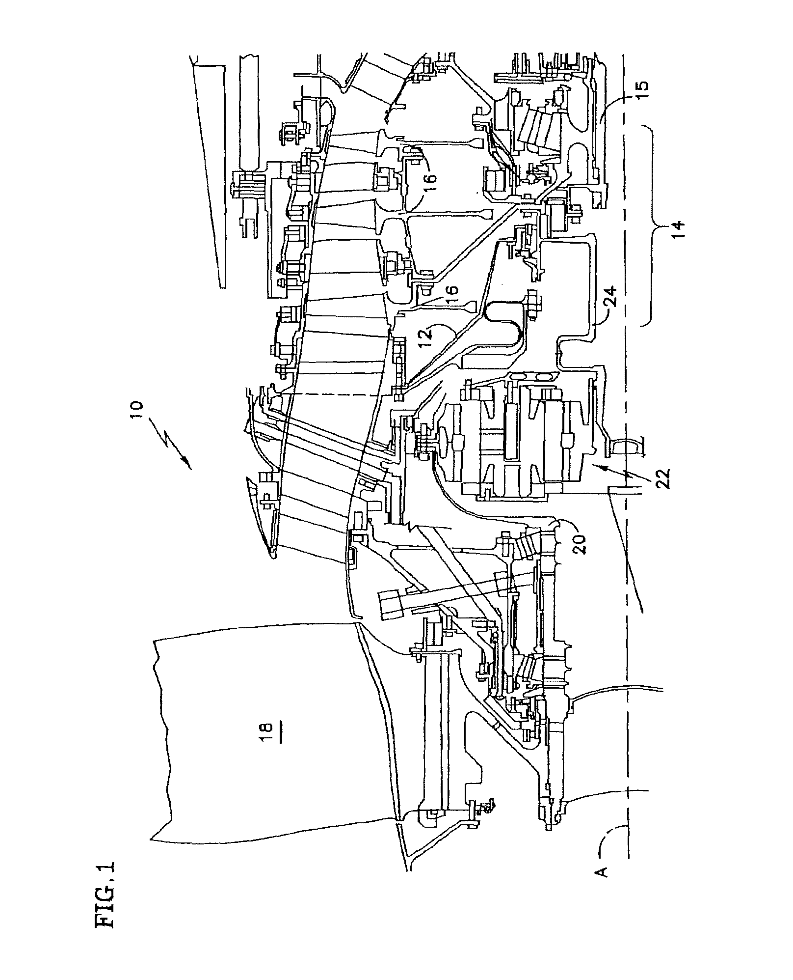
A portion of a gas turbine engine 10 is shown schematically in FIG. 1. The turbine engine 10 includes a fixed housing 12 that is constructed from numerous pieces secured to one another. A compressor section 14 having compressor hubs 16 with blades are driven by an engine shaft 15 about an axis A. A fan 18 is supported on a fan shaft 20 that is driven by a compressor shaft 24, which supports the compressor hubs 16, through an epicyclic gear train 22.

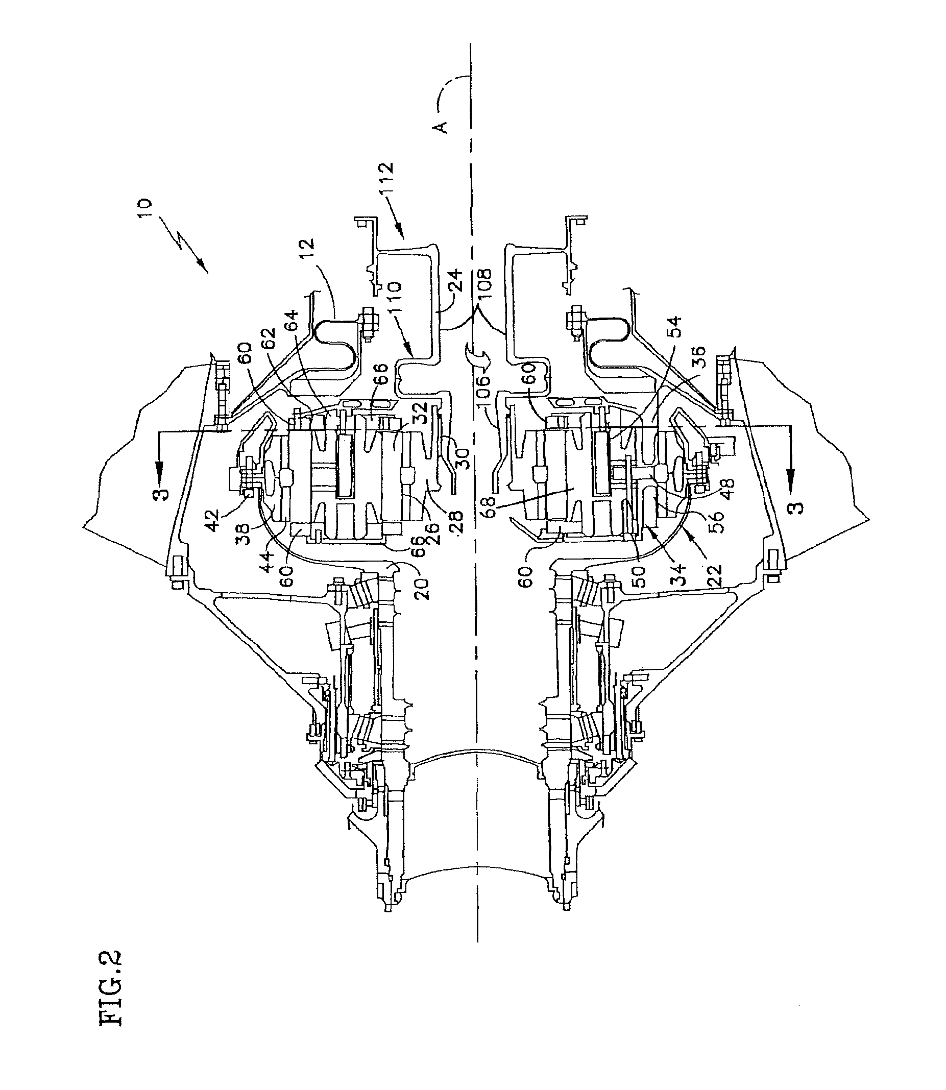
Referring to FIGS. 2 and 3, the compressor shaft 24 includes one or more annular shaft sections 106, 108 and one or more annular flexible linkages 110, 112. In the specific embodiment in FIG. 3, the compressor shaft includes a first shaft section 106, a second shaft section 108, a first flexible linkage 110, and a second flexible linkage 112.

Now referring to FIG. 3, each shaft section 106, 108 extends axially (e.g., parallel to the axis A) between a forward end 114, 116 and an aft end 118, 120. The first shaft section 106 has a wall thick...


PUM


Abstract

A shaft for a gas turbine engine is provided that includes a first shaft section, a second shaft section, a first flexible linkage, and a second flexible linkage. The first shaft section extends between a forward axial end and an aft axial end along a first axial centerline. The second shaft section extends between a forward axial end and an aft axial end along a second axial centerline. The first flexible linkage includes a bridge section connected between a first diaphragm and a second diaphragm. The first diaphragm is connected to the aft axial end of the first shaft section. The second diaphragm is connected to the forward axial end of the second shaft section. The second flexible linkage includes a diaphragm and a hub. The second flexible linkage diaphragm cantilevers radially outwardly from an inner radial end to an outer radial end, and is connected to the aft axial end of the second shaft section. The hub is connected to the outer radial end of the second flexible linkage diaphragm, and includes an engine shaft coupling connected to the hub.

Description

BACKGROUND OF THE INVENTION1. Technical FieldThis disclosure relates generally to shafts within a gas turbine engine in general, and to flexible shafts used within a gas turbine engine having an epicyclic gear train in particular.2. Background InformationGas turbine engines typically employ an epicyclic gear train connected to a turbine section of the engine, which is used to drive the fan section. In a typical epicyclic gear train, a sun gear receives rotational input from a turbine shaft through a compressor shaft. A carrier supports intermediate gears that surround and mesh with the sun gear. A ring gear surrounds and meshes with the intermediate gears. In arrangements in which the carrier is fixed against rotation, the intermediate gears are referred to as “star” gears and the ring gear is coupled to an output shaft that supports the turbo fan. In arrangements in which the ring gear is fixed against rotation, the intermediate gears are referred to as “planetary” gears and the ca...

Claims


Application Information

Patent Timeline
Patent Type & Authority Patents(United States)
IPC IPC(8): F02K3/02F04D25/02
CPCF01D5/06F01D5/066F01D25/18F02C7/36F16H1/48F05D2260/40311Y02T50/671F05D2240/62F16H1/227F16D3/72Y02T50/60
Inventor SHERIDAN, WILLIAM G.MCCUNE, MICHAEL E.PESCOSOLIDO, ALESSIO
Owner RTX CORP
Why Eureka
Try Eureka