Low noise fast dithering switching power supply

a switching power supply and low noise technology, applied in the field of switching power supplies, can solve the problems of generating ripple signals, reducing the tolerance of spurious transmissions, and reducing the frequency so as to achieve significant reduction or elimination of dithering frequency ripple

Active Publication Date: 2011-04-19
QORVO US INC
View PDF4 Cites 14 Cited by
  • Summary
  • Abstract
  • Description
  • Claims
  • Application Information

AI Technical Summary

Benefits of technology

[0004]The present invention is a switching power supply that switches (dithers) between at least two switching frequencies without introducing a ripple signal at the dithering frequency, which is based on the time duration of a dithering cycle. In one embodiment of the present invention, an average current in an energy transfer element, such as an inductive element, during operation using one switching frequency is regulated to be approximately equal to the average current during operation using any other switching frequency. The average current may be regulated by controlling the durations of transition periods between operating using one switching frequency and operating using another switching frequency. By maintaining a constant average current while operating using different switching frequencies, dithering frequency ripple may be significantly reduced or eliminated. The switching power supply may provide power to an RF power amplifier (PA), other circuitry, or both.

Problems solved by technology

Transmitter output spectrum requirements become more restrictive and less tolerant of spurious transmissions.
Third-generation (3G) and later mobile phone standards may be particularly restrictive.
However, one drawback to using a switching power supply to power a PA is that a switching power supply uses switching signals at a switching frequency and may generate a ripple signal at the switching frequency and at harmonics of the switching frequency.
The ripple signal may be coupled into the PA and appear at the PA's RF output, and may violate output spectrum requirements.

Method used


Image

  • Low noise fast dithering switching power supply
  • Low noise fast dithering switching power supply
  • Low noise fast dithering switching power supply

Examples


Embodiment Construction

[0021]The embodiments set forth below represent the necessary information to enable those skilled in the art to practice the invention and illustrate the best mode of practicing the invention. Upon reading the following description in light of the accompanying drawing figures, those skilled in the art will understand the concepts of the invention and will recognize applications of these concepts not particularly addressed herein. It should be understood that these concepts and applications fall within the scope of the disclosure and the accompanying claims.

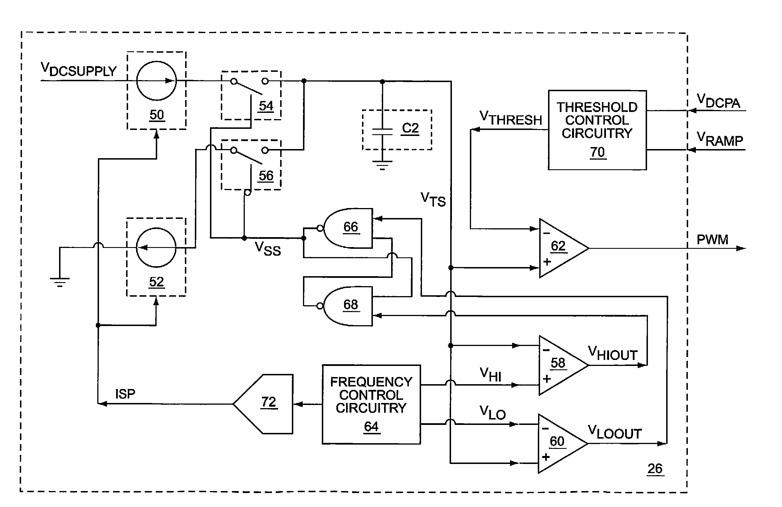
[0022]The present invention is a switching power supply that switches (dithers) between at least two switching frequencies without introducing a ripple signal at the dithering frequency, which is based on the time duration of a dithering cycle. In one embodiment of the present invention, an average current in an energy transfer element, such as an inductive element, during operation using one switching frequency is regulated to be...


PUM


Abstract

The present invention is a switching power supply that switches (dithers) between at least two switching frequencies without introducing a ripple signal at the dithering frequency, which is based on the time duration of a dithering cycle. In one embodiment of the present invention, an average current in an energy transfer element, such as an inductive element, during operation using one switching frequency is regulated to be approximately equal to the average current during operation using any other switching frequency. The average current may be regulated by controlling the durations of transition periods between operating using one switching frequency and operating using another switching frequency. By maintaining a constant average current while operating using different switching frequencies, dithering frequency ripple may be significantly reduced or eliminated.

Description

FIELD OF THE INVENTION[0001]The present invention relates to switching power supplies, which may be used in radio frequency (RF) communications circuits.BACKGROUND OF THE INVENTION[0002]With the growth of the wireless communications industry, wireless communications protocols become more sophisticated and demanding in their requirements for complex modulation schemes and narrow channel bandwidths. Transmitter output spectrum requirements become more restrictive and less tolerant of spurious transmissions. Third-generation (3G) and later mobile phone standards may be particularly restrictive.[0003]Switching power supplies are sometimes used to provide power to RF power amplifiers (PAs), since the efficiencies of switching power supplies can be fairly high. Additionally, the magnitudes of switching power supply outputs can be varied to maintain high efficiencies at different output power levels, or to amplitude modulate PAs. However, one drawback to using a switching power supply to p...

Claims


Application Information

Patent Timeline
Patent Type & Authority Patents(United States)
IPC IPC(8): G05F1/56G05F1/575
CPCH02M3/156
Inventor LEVESQUE, CHRISCOLLES, JOSEPH H.BERCHTOLD, JEAN-CHRISTOPHE
Owner QORVO US INC
Why Eureka
Try Eureka