Replacement cable marker pole having rotatable collar for attachment of pole to base

a technology of replacement cable and marker pole, which is applied in the field of marker poles, can solve the problems of large loss of earnings associated with inoperative fiber-optic cable, significant threat to buried utility lines, and inability to operate excavating equipment and operations, etc., and achieves the effects of avoiding explosion hazards, avoiding buried utility lines, and avoiding buried utilities

Inactive Publication Date: 2011-04-26
AMERICAN TELEPHONE & TELEGRAPH CO
View PDF14 Cites 42 Cited by
  • Summary
  • Abstract
  • Description
  • Claims
  • Application Information

AI Technical Summary

Problems solved by technology

However, because relatively high revenues are typically generated from their transfer of correspondingly large amounts of data for telecommunications customers, there exists the potential for large losses in earnings associated with an inoperative fiber-optic cable.
Excavating equipment and operations pose significant threats to buried utility lines, including fiber-optic cables.
Natural gas pipelines, for example, pose an explosion risk.
Electrical power lines have attendant risks of damage and injuries related to electrical power.
Accidentally severing a buried fiber-optic cable can subject an excavation contractor to significant liability for interrupted service.
Severing fiber-optic cables can interrupt service unless transmissions can be rerouted.
Depending upon the normal traffic volume in a buried cable, significant revenues can be lost before a splice can be made and service restored.
Although they are relatively easy to install, many of the prior art designs can be easily destroyed by impact with moveable objects.

Method used


Image

  • Replacement cable marker pole having rotatable collar for attachment of pole to base
  • Replacement cable marker pole having rotatable collar for attachment of pole to base
  • Replacement cable marker pole having rotatable collar for attachment of pole to base

Examples


first embodiment

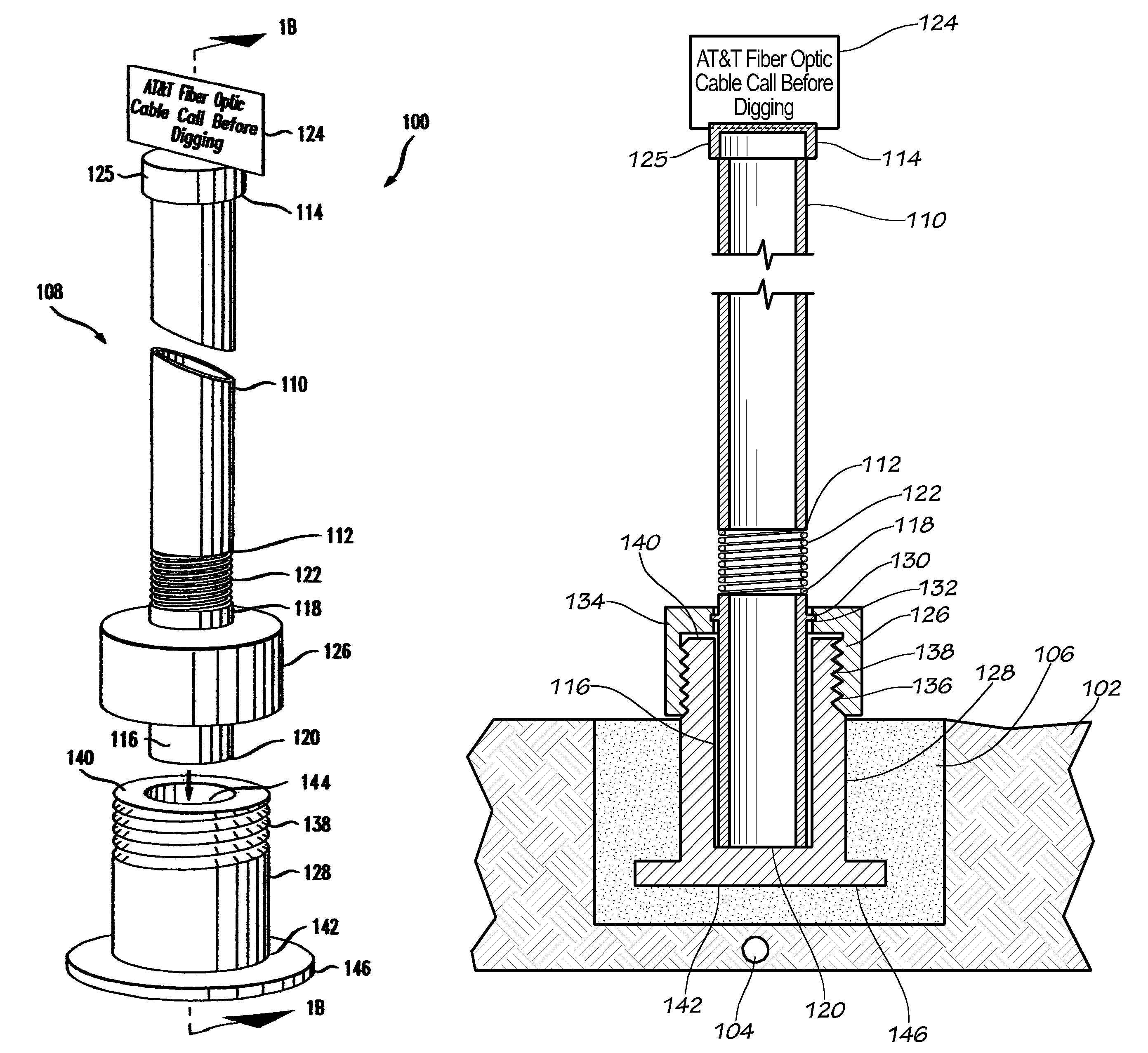
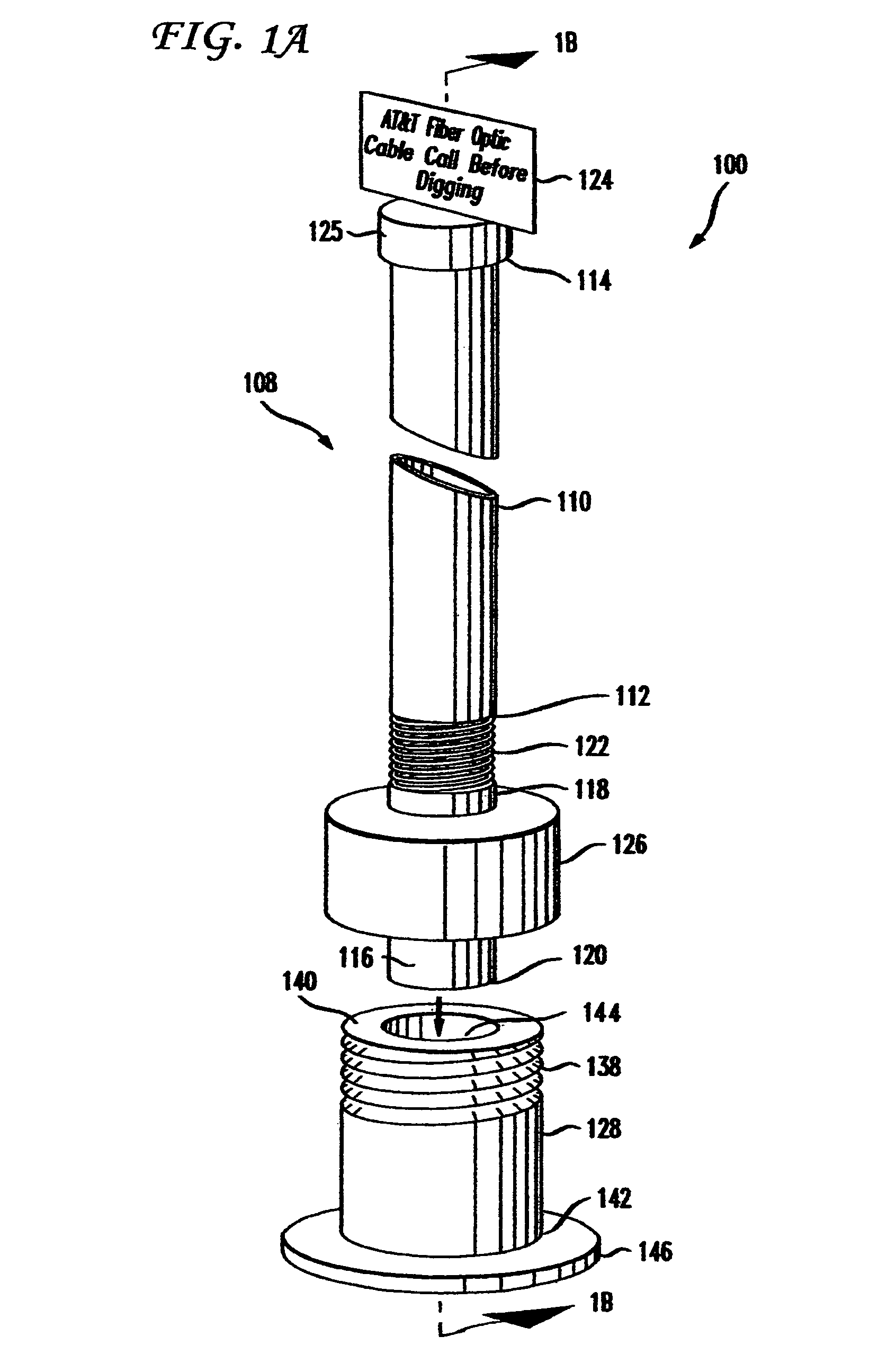
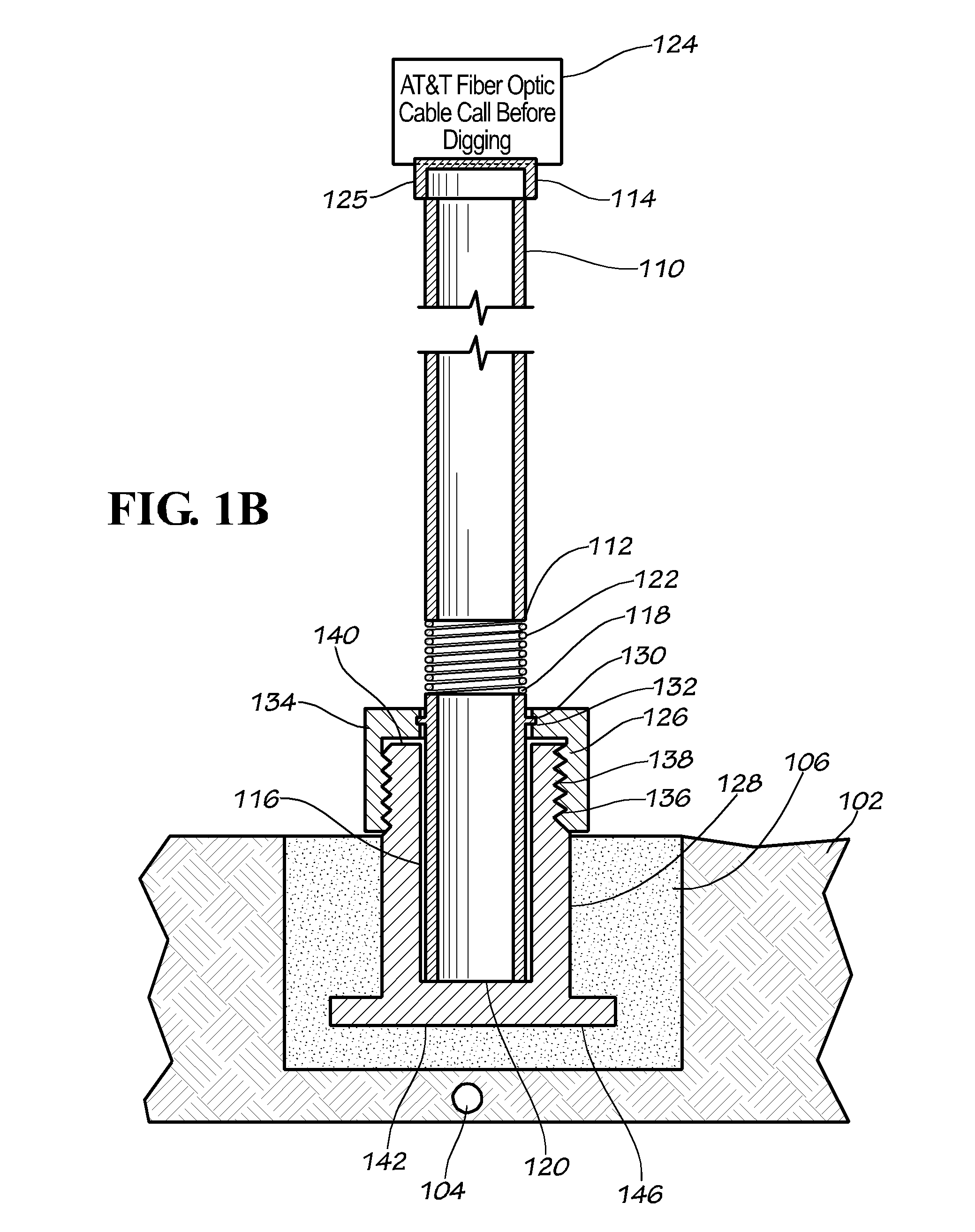
[0015]FIGS. 1A and 1B depict a marker pole system 100 in accordance with an aspect of the present invention. The marker pole system 100 is adapted to be partially embedded in the earth 102 over a buried utility line, such as a fiber optic cable 104. The marker pole system may be embedded in hardened earth or concrete generally represented by the reference numeral 106.

[0016]The marker pole system 100 includes a pole assembly 108 comprising a first elongated member 110 defining a first end 112 and a second end 114, and a second elongated member 116 defining a first end 118 and a second end 120. The first member 110 is connected to the second member 116 by a coil spring 122 that is attached to the first end 112 of first member 110 and the first end 118 of second member 116, respectively. The first member 110 preferably consists of an elongated section of plastic pipe (e.g., polyvinyl chloride (PVC)), approximately 6 to 8 feet in length. Although a circular tubular body is shown, rectan...

second embodiment

[0020]Referring now to FIGS. 2A and 2B, there is depicted a marker pole system 200 in accordance with an aspect of the invention. The marker pole system 200 includes a pole assembly 208 comprising a first elongated member 210 defining a first end 212 and a second end 214, and a second elongated member 216 defining a first end 218 and a second end 220. The first member 210 is connected to the second member 216 by a coil spring 222 that is attached to the first end 212 of first member 210 and the first end 218 of second member 216, respectively. A sign 224 is affixed to the second end 214 of the first member 210. The second member 216 is provided with a threaded portion 248 adapted to mate with a complimentary threaded portion defined in a base 228.

[0021]As in the first embodiment, the base 228 is preferably configured as a generally elongated tubular structure having a first end 240, a second end 242, and a centrally disposed elongated receptacle or bore 244 having a threaded portion...

third embodiment

[0022]Referring now to FIGS. 3A and 3B, there is depicted a marker pole system 300 in accordance with an aspect of the invention. The marker pole system 300 comprises a pole assembly 308 comprising a first elongated member 310 defining a first end 312 and a second end 314, and a second elongated member 316 defining a first end 318 and a second end 320. The first member 310 is connected to the second member 316 by a coil spring 322 that is attached to the first end 312 of first member 310 and the first end 318 of second member 316, respectively. A sign 324 is affixed to the second end 314 of the first member 310.

[0023]A base 328 is preferably configured as a generally elongated tubular structure having a first end 340, a second end 342, and a centrally disposed elongated receptacle or bore 344 sized and adapted for receiving a portion of the second member 316 of the pole assembly 308. As in the first and second embodiments, the base 328 may be provided with a flange 346 to prevent th...


PUM


Abstract

A cable marker pole system is described for marking the location of buried utility cabling. The cable marker pole system includes a base for embedding in earth or concrete, and a two-part pole assembly that couples with the base. The two-part pole assembly includes a spring coupling the two pole members to allow the pole assembly to flex if struck. A sign is attached to the top of the pole assembly to indicate what is buried.

Description

BACKGROUND OF THE INVENTION[0001]The present invention relates generally to marker poles for subterranean cable installations, and more particularly, to a marker pole having a spring-loaded portion extending above the ground to facilitate movement thereof in response to impacts from motor-vehicles, lawn mowers and the like.[0002]Marker poles are commonly employed for marking the locations of various underground objects. For example, utility lines are often buried in the ground in many locations for aesthetic reasons. Marker poles are placed in the ground and disposed along the buried cable in order to show the location thereof.[0003]In recent years fiber-optic cable networks have been installed in many parts of the country. A common installation procedure involves trenching or boring underground and placing the fiber-optic cables within protective plastic conduit. The fiber-optic cables have many advantages for telecommunications, including the ability to efficiently transmit large ...

Claims


Application Information

Patent Timeline
Patent Type & Authority Patents(United States)
IPC IPC(8): E01F9/013F16M13/00E01F9/017E01F9/677E01F9/627
CPCE04H12/2269E01F9/0175E01F9/629
Inventor ESLAMBOLCHI, HOSSEINHUFFMAN, JOHN SINCLAIRGEREN, GENE
Owner AMERICAN TELEPHONE & TELEGRAPH CO
Why Eureka
Try Eureka