Automated material handling system with load transfer vehicles

a technology of automatic material handling and load transfer vehicle, which is applied in the direction of passenger handling apparatus, special-purpose vessels, tractors, etc., can solve the problems of increasing not only the number of workers or crew members needed, but also the labor intensity and maintenance costs of the above-conventional material handling system, so as to achieve the effect of increasing safety

Inactive Publication Date: 2011-04-26
GEBRR BECKER
View PDF23 Cites 153 Cited by
  • Summary
  • Abstract
  • Description
  • Claims
  • Application Information

AI Technical Summary

Benefits of technology

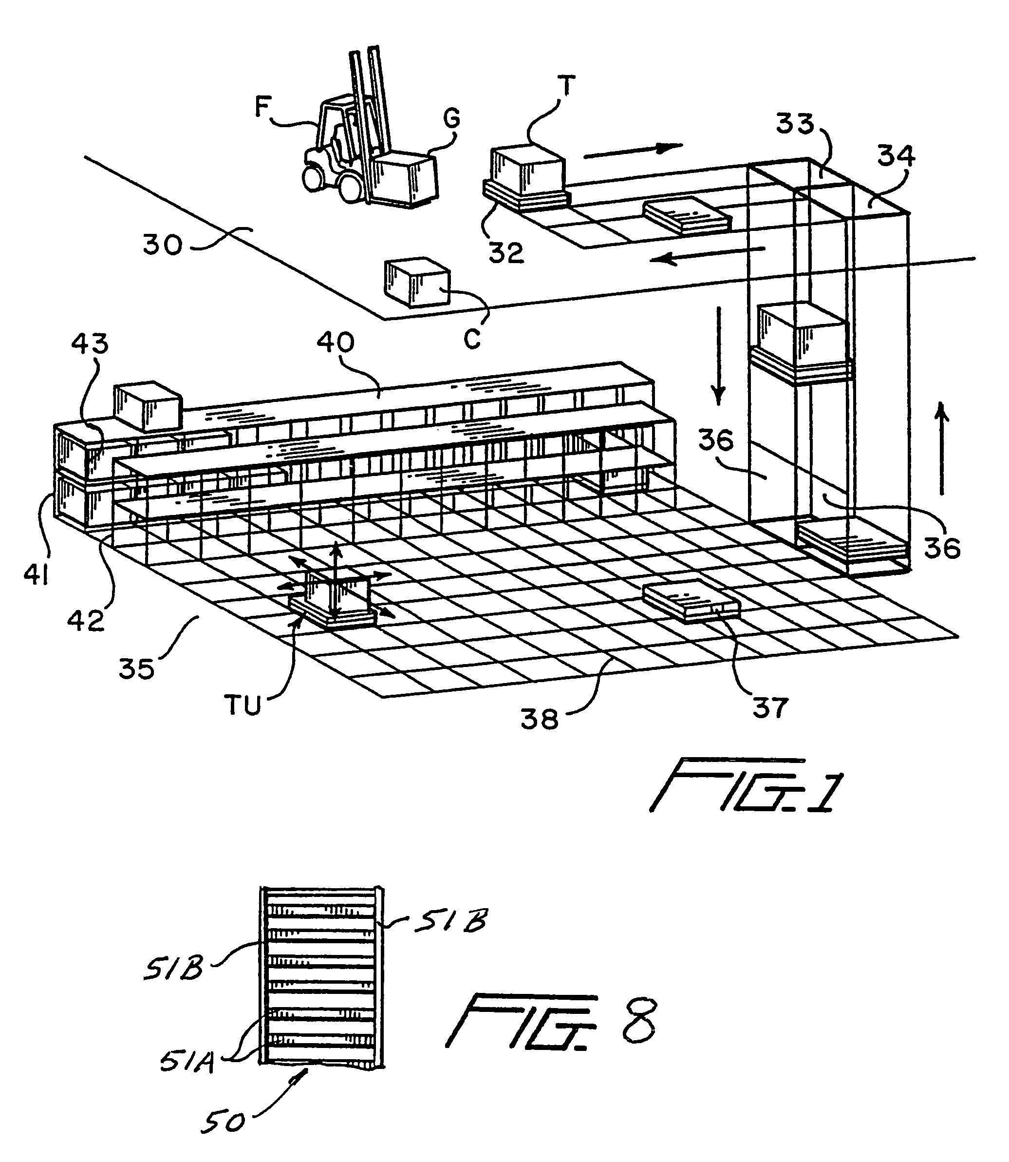
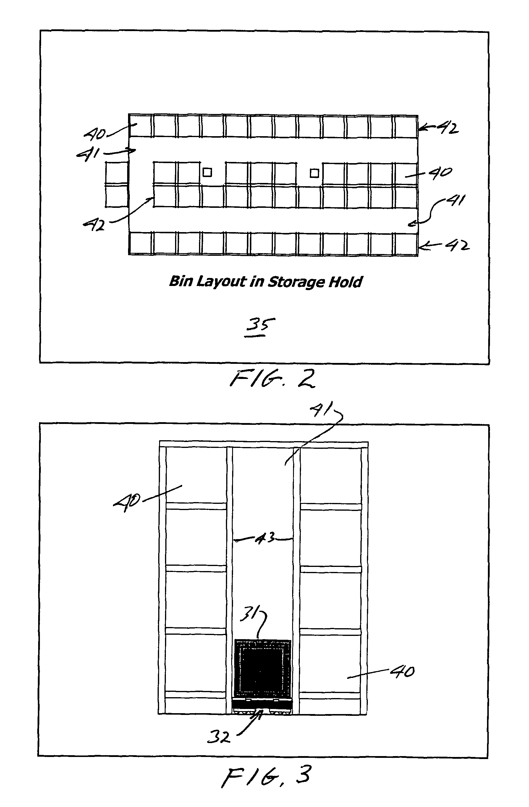
[0009]With the present invention, each of the load transfer units or vehicles has a first drive system which allows generally universal or omni-directional movement of the vehicles across horizontal levels, such as floors and decks, such that the vehicles may be maneuvered relative to storage bins which are provided in horizontally and vertically spaced arrangements within storage areas. Further, first motors or drive mechanisms associated with the first drive system may be manually or remotely controlled or subject to on-board programmable controllers associated with each vehicle. In some embodiments, the transfer vehicles may be self-loading and / or off-loading so that goods may be placed into or removed from storage bins without worker or crew member effort.
[0024]It is yet another object of the present invention to provide automated material and article handling systems which are particularly adapted for warehouses and ocean going vessels wherein increased safety is achieved by providing systems which allow for self-loading and unloading of transfer vehicles and subsequent movement of goods and equipment to desired locations without manual intervention, other than through manual remote control of the transfer vehicles.

Problems solved by technology

The above conventional material handling systems are very labor intensive and costly to maintain.
In facilities having multiple storage floors and on ocean going vessels having multiple decks, the use of multiple load carrying vehicles or machinery at different levels increases not only the number of workers or crew members necessary to effectively distribute goods but also requires duplication of equipment at each level for maneuvering large, heavy and bulky items.

Method used


Image

  • Automated material handling system with load transfer vehicles
  • Automated material handling system with load transfer vehicles
  • Automated material handling system with load transfer vehicles

Examples


first embodiment

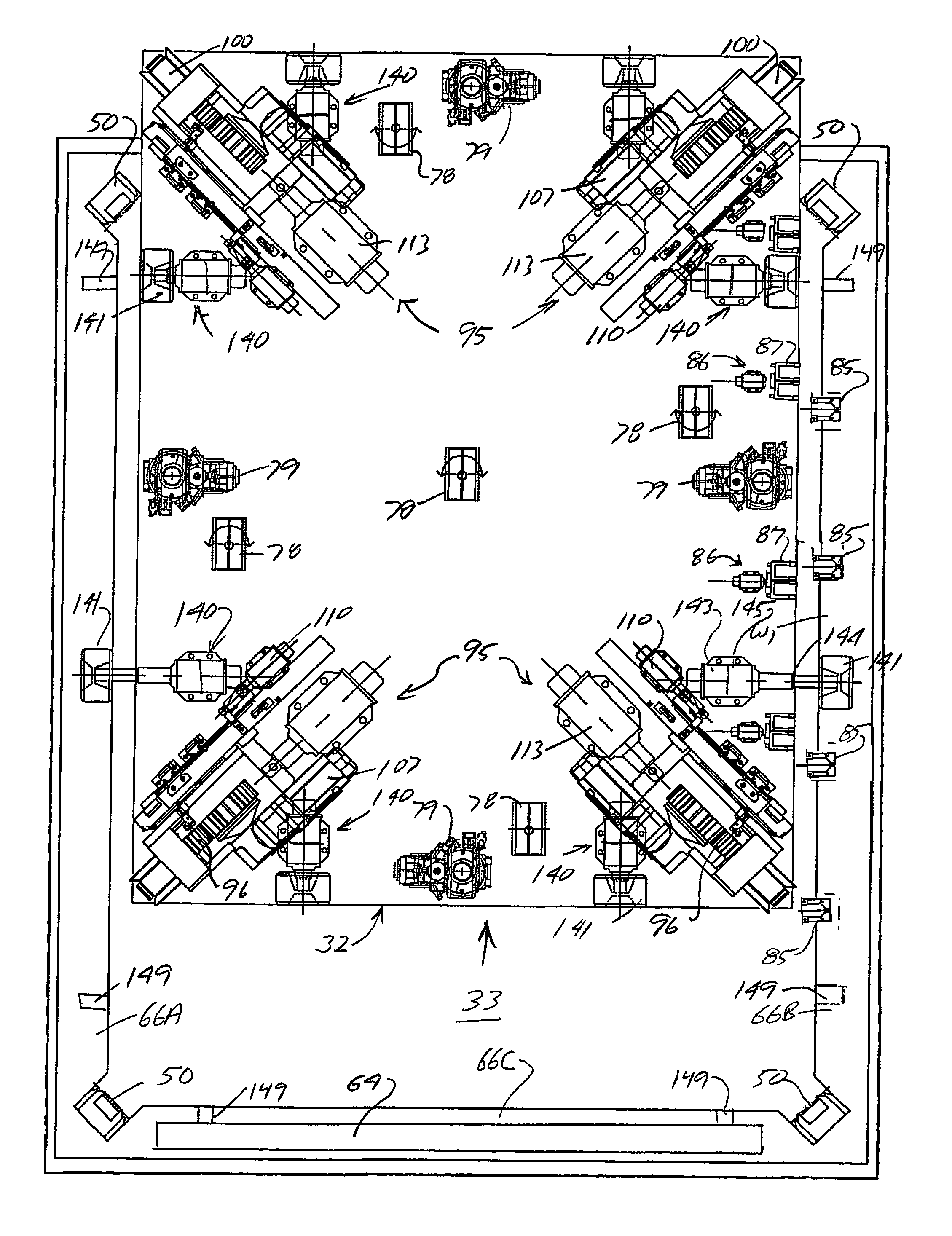
[0080]With specific reference to FIG. 6, load transfer vehicle 32 is disclosed in greater detail. In this embodiment, the vehicle includes a body or frame having an upper surface 70, lower surface 71, front end 72 and rear ends, and opposite sides 74 and 75. A pair of spaced and opposing generally parallel L-shaped tracks 76 are secured to the upper surface on which various storage containers or pallets 31, as previously described, are selectively supported when being transported. As opposed to separate spaced tracks 76, a substantially continuous support surface may be provided along the upper surface of the vehicle. In some embodiments, upwardly extending supports 77 are mounted, such as by welding, to the upper surface of the frame and adjacent the sides thereof. An electronic programmable controller 83 for the vehicle is mounted to one of the supports 77 and may include a number of communication and computer elements for automatically controlling the movement of the vehicle as d...

second embodiment

[0092]vertical drive assemblies 95′ are slightly modified and the gear racks 50 are mounted to opposing side walls of a trunk spaced inwardly from the corners as opposed to the corner mounting described above. With specific reference to FIGS. 6 and 21-23, the modified vertical drive assemblies also include a drive pinion 96′ that is rotatably and slightly floatably mounted between inner and outer support plates 97′ and 98′ of a bracket assembly 99′ so as to be intermediate upper and lower guide rollers 100′ and 101′, respectively, that are also rotatably carried by the bracket assembly. The inner support plate 97′ is also mounted on a movable carriage plate 109′ that is reciprocally mounted within a guide housing 103′ that is fixed to the frame of the transfer vehicle. In this embodiment, a pinion drive assembly 105′ is mounted to the carriage plate 109′ and includes a drive shaft, to which the pinion gear 96′ is secured and that is driven by an output of an electric motor 107′ by w...


PUM


Abstract

A material handling system for use in storing and moving goods within multi-level storage warehouses, ocean going vessels and the like wherein storage areas are provided on at least one of the levels and wherein goods are automatically transferred to and from the storage areas and between the various levels by self-propelled load transfer vehicles. The load transfer vehicles move across the surface of the various levels and are also movable under their own power within open vertical trunks between the levels to thereby move goods to any desired area within the system, warehouse or vessel.

Description

CROSS REFERENCE TO RELATED APPLICATIONS[0001]This application is a continuation-in-part of co-owned U.S. application Ser. No. 10 / 429,784, filed May 6, 2003, entitled Automated Material Handling System With Motorized Transfer Vehicles.BACKGROUND OF INVENTION[0002]1. Field of the Invention[0003]The present invention is directed to automated material and article handling systems which can be used in any multi-level warehouse, storage and / or distribution environment, including ocean going vessels, such as naval ships. Each system includes a plurality of vertically spaced levels where goods are either stored, delivered to or taken from, or temporarily positioned. In some systems, one or more levels may be designated as goods receiving and storage levels, such as in cargo holds of ships, in which goods or cargo may be selectively stored, sometimes in vertically and horizontally spaced bins, racks or shelves. In preferred embodiments, the goods are carried on pallets that are moved by self...

Claims


Application Information

Patent Timeline
Patent Type & Authority Patents(United States)
IPC IPC(8): B65G1/00
CPCB63B25/22B66B9/00B65G1/0478B65G1/04B65G1/0492Y02B50/00
Inventor BENEDICT, CHARLES E.PFEIFER, BRIAN G.YATES, CHRISTIAN A.BLADEN, SCOTT K.DOBBS, JAMES R.
Owner GEBRR BECKER
Why Eureka
Try Eureka