
Orthodontic anchor

a technology for orthodontics and anchors, applied in the field of orthodontics, can solve the problems of undesirable displacement of anchor teeth, such as molars, and achieve the effect of facilitating easy placement in the mouth and reducing adverse reactions

Inactive Publication Date: 2011-04-26
SCHENDEL STEPHEN A
View PDF41 Cites 5 Cited by
  • Summary
  • Abstract
  • Description
  • Claims
  • Application Information

AI Technical Summary

Benefits of technology

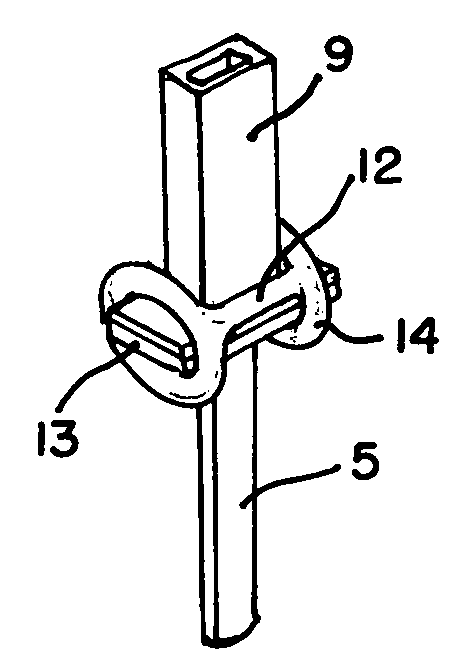
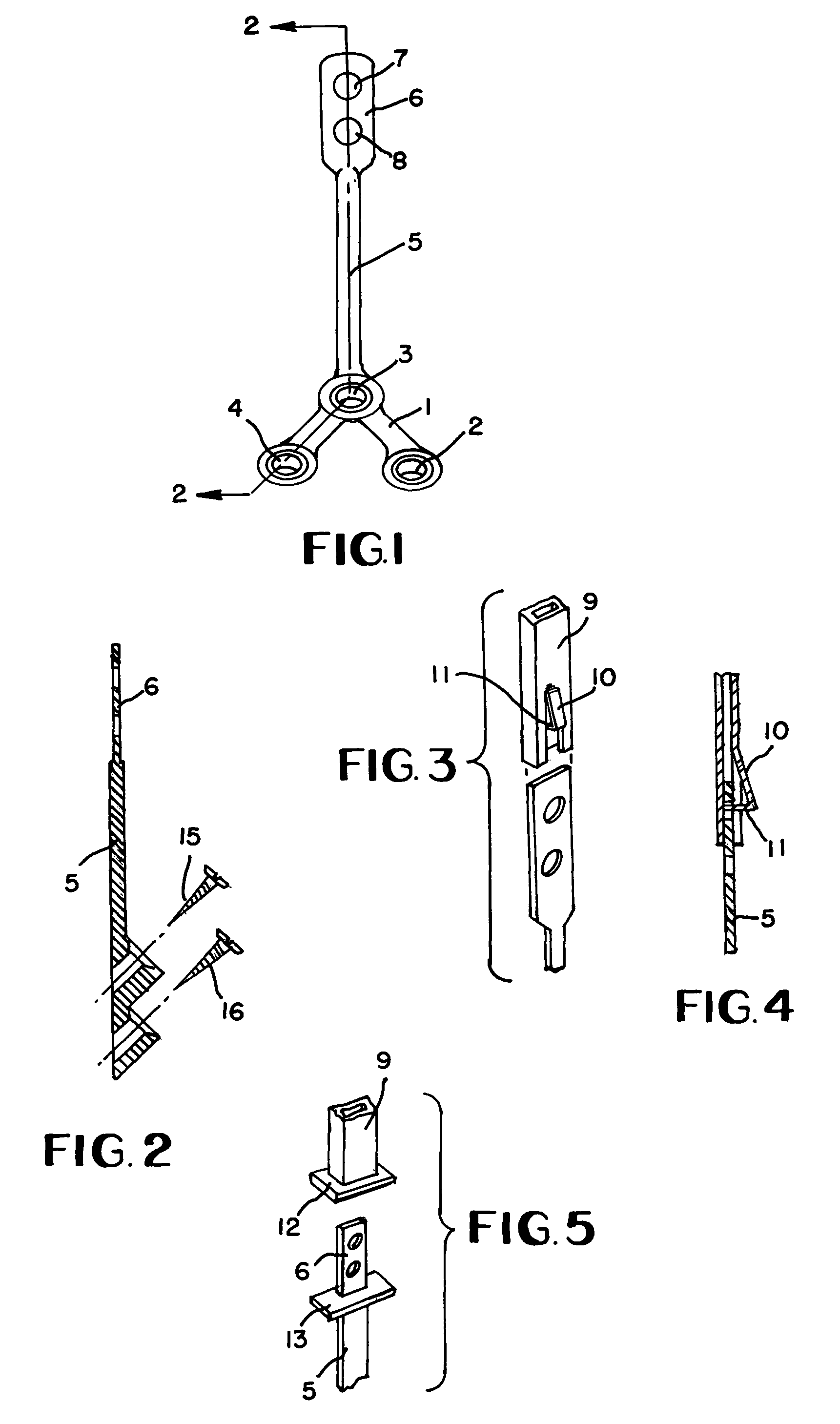
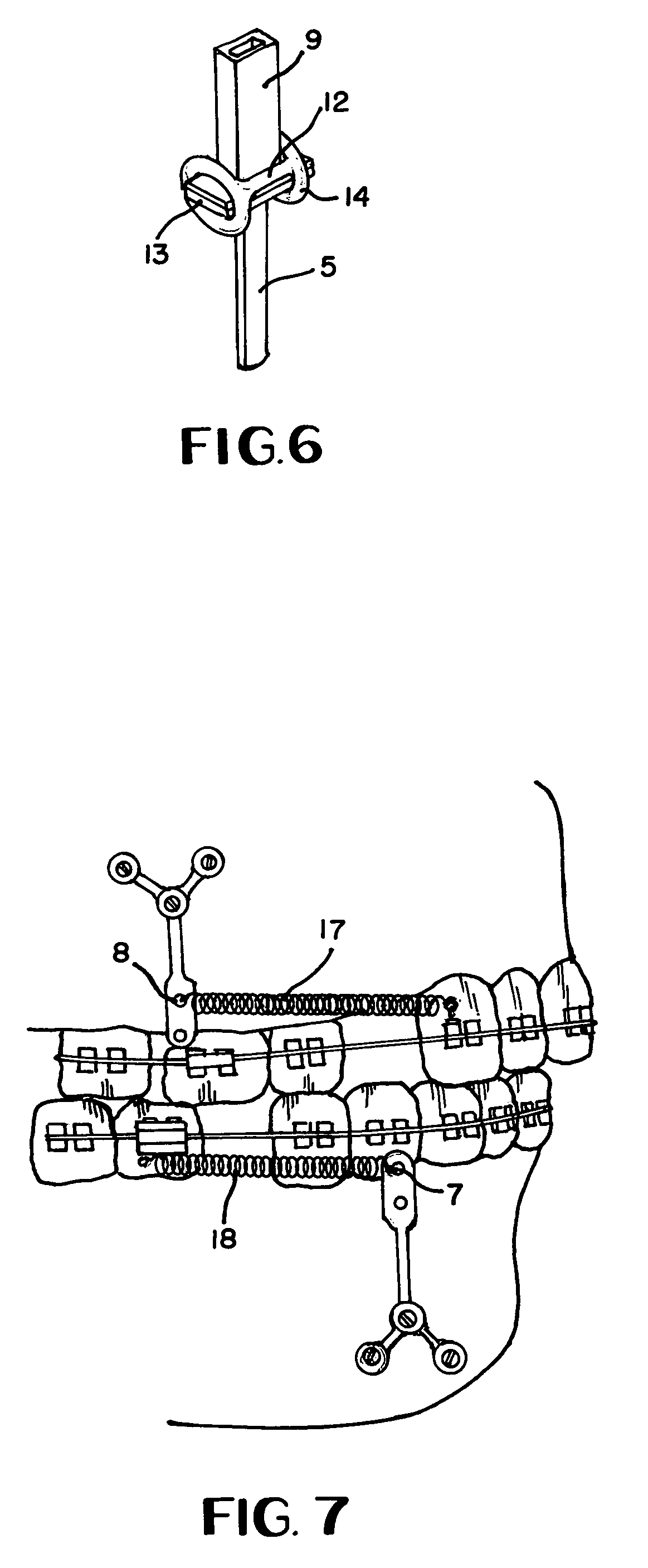
[0004]By this invention, an orthodontic anchor comprises a thin plate secured to the bone by means of screws which are placed through angled apertures formed in the thin plate which facilitates easier placement in the mouth. The emerging end of the plate includes apertures for attachment of orthodontic devices such as springs and the like. In addition, a metal cap is attachable to the free end of the anchor to which various orthodontic devices, such as brackets of various types, may be affixed by any known means such as soldering. Also the length of the anchor between the screw bearing end and the emerging end is round or rectangular for ease of bending and passing through the gingival tissues with little adverse reaction. A first transverse rib is formed on the lower edge of the cap and a second transverse rib is integrally joined to the anchor and an elastic band envelopes both transverse ribs.

Problems solved by technology

Oftentimes the anchor teeth, such as molars, tend to be displaced in an undesirable fashion due to reverse tension forces occurring during orthodontic treatment.

Method used


Image

  • Orthodontic anchor
  • Orthodontic anchor
  • Orthodontic anchor

Examples


Embodiment Construction

[0013]With reference to the drawings, and in particular FIG. 1, the orthodontic anchor according to this invention is shown and which is generally planar in configuration and including Y-shaped connecting portion 1 having beveled apertures 2, 3 and 4 formed therein. Of course, connecting portion 1 can be of varying shapes besides that shown in FIG. 1 such as an L-shaped configuration. In addition, any number of apertures may be employed and may be disposed at any location on the connecting portion as dictated by the location requirements of the particular orthodontic application.

[0014]The anchor shown in FIG. 1 further includes elongated stem 5 with emerging portion or top end 6 formed thereon remote from Y-shape connecting portion 1. Stem 5 is generally round or rectangular so that it can be easily bent for proper placement of connecting portion 1. Apertures 7 and 8 are formed in emerging portion 6, the number and location of which are variable, as desired.

[0015]With reference to F...


PUM


Abstract

An orthodontic anchor having a stem with a connecting portion and an emerging portion secured respectively to the ends thereof. The connecting portion is connected to bone by screws disposed in angled apertures and a cap envelops the emerging portion. A first transverse rib secured to the lower edge of the cap and a second transverse rib secured to the anchor between the connecting and emerging portions and an elastic band enveloping both transverse ribs.

Description

[0001]This is a division of patent application Ser. No. 11 / 784,566 filed Apr. 9, 2007 now abandoned.BACKGROUND OF THE INVENTION[0002]It is well known in orthodontics to affix brackets to individual teeth and then fasten an archwire to the brackets such that a tension force is initiated in the desired direction between individual teeth. The resilience of the archwire ultimately results in the desired dentition. Oftentimes the anchor teeth, such as molars, tend to be displaced in an undesirable fashion due to reverse tension forces occurring during orthodontic treatment.[0003]By anchoring an orthodontic appliance to the bone of the mandible or maxilla in order to apply force to certain teeth, the anchor teeth are alleviated from any movement which permits more efficacious correction of the dentition. In addition, attachment of the anchor to bone allows for the positioning of the anchor at the most desirable location to apply the optimum correcting force.BRIEF SUMMARY OF THE INVENTION[...

Claims


Application Information

Patent Timeline
IPC IPC(8): A61C7/00
CPCA61C7/00A61C8/0096Y10T24/45005Y10T24/44231Y10S24/31
Inventor SCHENDEL, STEPHEN A.
Owner SCHENDEL STEPHEN A
Learn More