Connector with side flange

a technology of side flanges and connectors, which is applied in the direction of coupling contact members, coupling device connections, engagement/disengagement of coupling parts, etc., can solve the problems of increasing the size and cost of electronic appliances, occupying excessive space for socket connectors, and using more screws, so as to reduce the need for mounting space, not easily bent, and saving manufacturing costs

Inactive Publication Date: 2011-04-26
MOLEX INC
View PDF13 Cites 0 Cited by
  • Summary
  • Abstract
  • Description
  • Claims
  • Application Information

AI Technical Summary

Benefits of technology

[0007]The present invention provides an electrical connector which can be stably fixed on an electrical appliance. Particularly, when several connectors of the present invention are disposed side by side, a reduction in space can be realized. This advancement will allow the dimensions of new electrical appliances to continue to become smaller.
[0010]The mounting portions disposed on the two sides of the electrical connector of the present invention are at different mounting levels. When the plurality of electrical connectors are disposed together side by side, the mounting portions of the adjacent electrical connectors mutually contact each other in a front-to-rear manner. Therefore, the required mounting space is reduced and manufacturing cost is saved. In addition, the mounting portions of the electrical connector of the present invention have fixing feet which can equally resist forces while being mounted to a printed circuit board. The mounting portions are not easily bent so it achieves a stable fixing objective.

Problems solved by technology

However, the depicted combination of socket connectors 8 takes excessive space and uses more screws 9 for parallel mounting than is desired.
Consequently, this combination tends to increase the size and cost of the electronic appliance.
In addition, because the mounting portion 830 is a simple sheet-like structure, excessive fastening force can cause the mounting portion 830 to be deformed during assembly, thus reducing the security of the attachment.

Method used


Image

  • Connector with side flange
  • Connector with side flange
  • Connector with side flange

Examples


Embodiment Construction

[0021]To make the features of the present invention more comprehensible, the present invention is further illustrated below through its preferred embodiments.

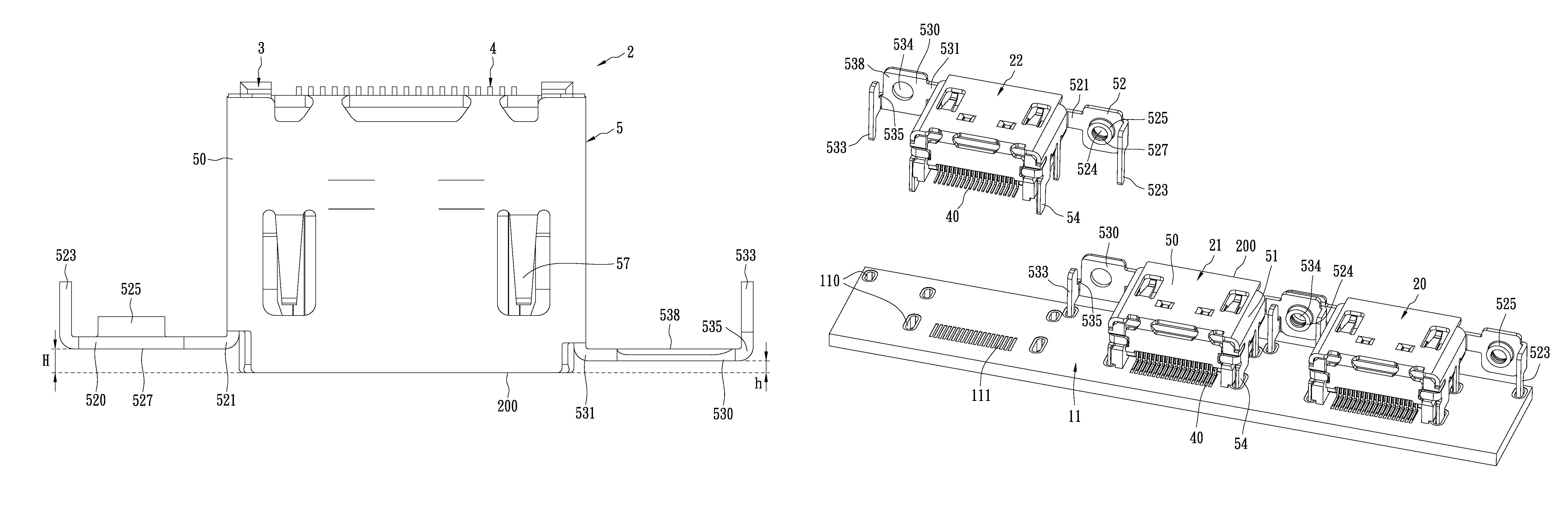
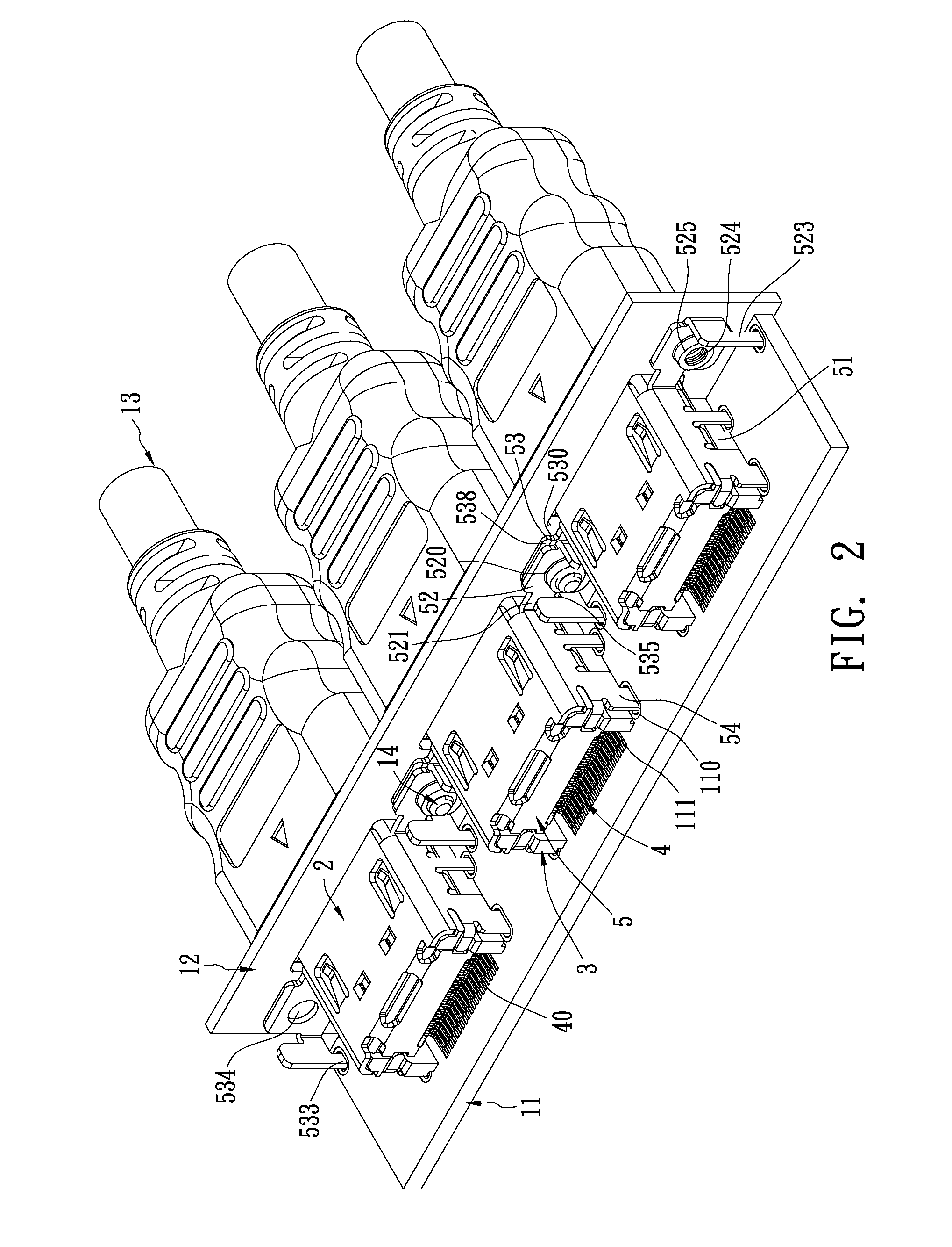
[0022]As shown in FIG. 2, electrical connectors 2 in accordance with an embodiment of the present invention are socket connectors, and they are disposed on the circuit board 11 of an electronic appliance (not shown) in a row. The electrical connectors 2 are further mounted on the shell 12 of the electronic appliance, and their insertion sides 200 are for corresponding plugs to be inserted into (as shown in FIGS. 3 and 5). For simplifying the following description, the side that the electrical connector 2 faces the circuit board 11 is defined as a lower side, and the opposite side is defined as an upper side; the insertion side 200 is defined as a front side, and the opposite side is defined as a rear side.

[0023]Further in view of FIGS. 3, 4 and 5, each of the electrical connectors 2 comprises an insulation body 3, a plurality o...


PUM


Abstract

An electrical connector comprises an insertion side and a shielding shell. The shielding shell comprises a frame, and further comprises a first mounting portion and a second mounting portion which may be respectively located on two opposing sides of the frame. Each of the first mounting portion and the second mounting portion has a fixing hole, and each has a front surface and a rear surface opposite the front surface. The rear surface of the second mounting portion and the front surface of the first mounting portion are substantially on the same plane.

Description

BACKGROUND OF THE INVENTION[0001]1. Related Cases[0002]This application claims priority to Taiwanese Patent Application No 097207348, filed Apr. 29, 2008, and to Chinese Patent Application No 200820110676.6, filed Apr. 30, 2008, both of which are incorporated herein by reference in their entirely.[0003]2. Field of the Invention[0004]The present invention relates to an electrical connector, and more particularly to an electrical connector having a mounting structure with an improved shielding shell.[0005]3. Description of the Related Art[0006]As consumer electronics technologies continue to progress, the market demands electronic appliances to be increasingly integrated into single units that can provide additional functions. In addition, consumers want electronic appliances to have small, lightweight and attractive designs. Therefore, it is beneficial to provide electronic appliances that are compact while still providing interfaces that can provide the additional functions. For exa...

Claims


Application Information

Patent Timeline
Patent Type & Authority Patents(United States)
IPC IPC(8): H01R13/62
CPCH01R13/748H01R13/65802H01R12/716H01R12/724H01R13/6582H01R13/658
Inventor TSENG, TING-CHANG
Owner MOLEX INC
Why Eureka
Try Eureka