System and method for treating ischemic stroke

a technology of ischemic stroke and system, applied in the field of medical treatment, can solve the problems of ischemic stroke, death and disability, and a growing problem in global healthcare, and achieve the effects of improving the situation, reducing the risk of stroke, and improving the risk of strok

Active Publication Date: 2011-04-26
PENUMBRA
View PDF101 Cites 175 Cited by
  • Summary
  • Abstract
  • Description
  • Claims
  • Application Information

AI Technical Summary

Problems solved by technology

Stroke is a leading cause of death and disability and a growing problem to global healthcare.
Even more disturbing, this already troubling situation is expected to worsen as the “baby boomer” population reaches advanced age, particularly given the number of people suffering from poor diet, obesity and / or other contributing factors leading to stroke.
Between the two types of strokes, ischemic stroke comprises the larger problem, with over 600,000 people in the US suffering from ischemic stroke per year.
Notwithstanding these generally favorable aspects, significant drawbacks exist with the use of pharmacologic treatment.
One such drawback is the relatively long amount of time required for the thrombolytics and / or anticoagulants to take effect and restore blood flow.
Given the time-critical nature of treating ischemic stroke, any added time is potentially devastating.
Another significant drawback is the heightened potential of bleeding or hemorrhaging elsewhere in the body due to the thombolytics and / or anticoagulants.
Although an improvement over pharmacologic treatments for ischemic stroke, such coil-based retrieval systems have only enjoyed modest success (approximately 55%) in overcoming ischemic stroke due to thromboembolic material slipping past or becoming dislodged by the coil.
Again, although overcoming the drawbacks of pharmacologic treatment, this nonetheless suffers a significant drawback in that the act of manipulating the basket or net structure distally from the occluded segment without angiographic roadmap visualization of the vasculature increases the danger of damaging the vessel.
Although generally safe, removal via aspiration is only effective with relatively soft thrombus-emboli.
While this rotating blade feature improves the effectiveness of such an aspiration technique, it nonetheless increases the danger of damaging the vessel due to the rotating blade.

Method used


Image

  • System and method for treating ischemic stroke
  • System and method for treating ischemic stroke
  • System and method for treating ischemic stroke

Examples


Embodiment Construction

[0044]Illustrative embodiments of the invention are described below. In the interest of clarity, not all features of an actual implementation are described in this specification. It will of course be appreciated that in the development of any such actual embodiment, numerous implementation-specific decisions must be made to achieve the developers' specific goals, such as compliance with system-related and business-related constraints, which will vary from one implementation to another. Moreover, it will be appreciated that such a development effort might be complex and time-consuming, but would nevertheless be a routine undertaking for those of ordinary skill in the art having the benefit of this disclosure. The thromboembolic removal system disclosed herein boasts a variety of inventive features and components that warrant patent protection, both individually and in combination.

System Features

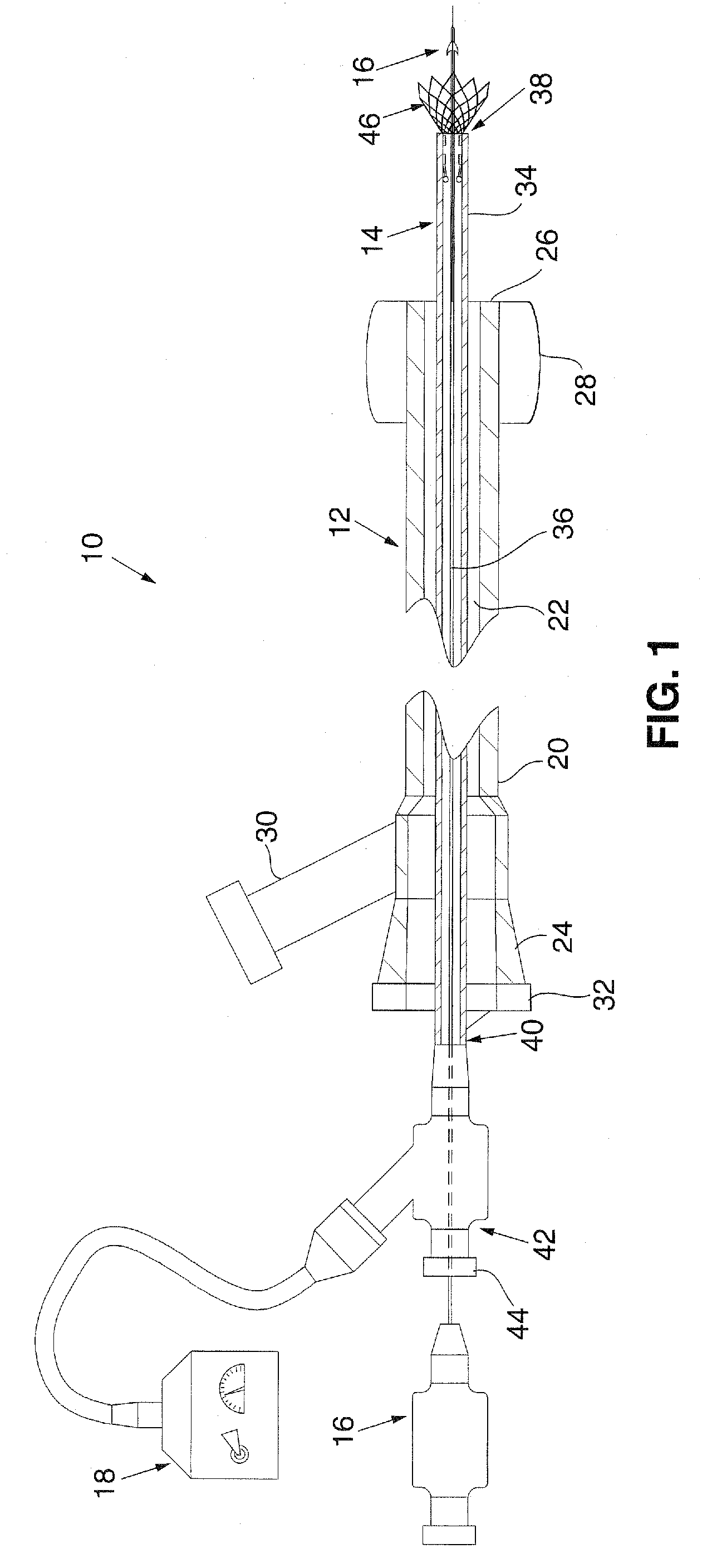
[0045]FIG. 1 illustrates an exemplary embodiment of a thromboembolic removal system 10. Th...


PUM


Abstract

A thromboembolic removal system for treating ischemic stroke includes an elongate member and a receiver on a distal portion of the elongate member. The receiver includes structural members arranged to form a sleeve having a central lumen. A plurality of the structural members form engaging elements having apex regions that extend into the central lumen. During use of the thromboembolic removal system, the receiver is advanced over a body of thromboembolic material within a blood vessel, causing the body to be received into the central lumen, and causing the engaging elements to engage the body within the lumen.

Description

[0001]This application claims priority to U.S. Provisional Application No. 60 / 609,028 filed Sep. 10, 2004, U.S. Provisional Application No. 60 / 669,779, filed Apr. 8, 2005, and U.S. Provisional Application No. 60 / 680,605, filed May 13, 2005, each of which is fully incorporated herein by reference.BACKGROUND OF THE INVENTION[0002]I. Field of the Invention[0003]The present invention relates generally to the field of medical treatment and, more particularly, to a system and method for treating ischemic stroke which involves removing a thromboembolism from a cerebral artery of a patient.[0004]II. Discussion of the Prior Art[0005]Stroke is a leading cause of death and disability and a growing problem to global healthcare. In the US alone, over 700,000 people per year suffer a major stroke and, of these, over 150,000 people die. Even more disturbing, this already troubling situation is expected to worsen as the “baby boomer” population reaches advanced age, particularly given the number of...

Claims


Application Information

Patent Timeline
Patent Type & Authority Patents(United States)
IPC IPC(8): A61M29/00A61B17/22
CPCA61B17/22A61B17/221A61B2017/22044A61M2025/1052A61B2217/005A61F2/013A61B2017/2215
Inventor BOSE, ARANIGUPTA, VIKASDONAHUE, SEANHUI, DELILAH
Owner PENUMBRA
Why Eureka
Try Eureka