System for tracking the location of components, assemblies, and subassemblies in an automated diagnostic analyzer

a technology of automated diagnostic analyzer and tracking system, which is applied in the field of tracking system, can solve the problems of high cost, increased power consumption, and high cost of radio frequency identification tags that utilize ultra-high frequency radio waves

Inactive Publication Date: 2011-04-26
ABBOTT LAB INC
View PDF8 Cites 136 Cited by
  • Summary
  • Abstract
  • Description
  • Claims
  • Application Information

AI Technical Summary

Benefits of technology

[0031](b) ability to provide supply chain visibility for the components, the assemblies, and the sub-assemblies of the medical instrument;

Problems solved by technology

However, radio frequency identification tags that utilize ultra-high frequency radio waves require more power than do radio frequency identification tags that utilize low frequency radio waves and are less likely to pass through materials such as liquids and metals.
However, active and semi-passive radio frequency identification tags are more expensive than are passive radio frequency identification tags, thereby making their cost too expensive for objects having a low value.
However, the Class 0 radio frequency identification tags and the Class 1 radio frequency identification tags did not provide the data functionality nor did they meet geographic RF emission requirements across the world.
This procedure can lead to transcription errors and missing or inaccurate information.
The manually recorded information is not readily accessible or traceable, and is not in a form that can be communicated to those who need to know the status regarding the configurations of the numerous medical instruments in assorted locations over a wide geographical area.

Method used


Image

  • System for tracking the location of components, assemblies, and subassemblies in an automated diagnostic analyzer
  • System for tracking the location of components, assemblies, and subassemblies in an automated diagnostic analyzer
  • System for tracking the location of components, assemblies, and subassemblies in an automated diagnostic analyzer

Examples


example

[0093]The following equipment was used to demonstrate the operation of the configuration management system described herein:

[0094]Medical Instrument:

[0095]ARCHITECT® i2000 immunoassay analyzer was used. (De-energized, i.e., not plugged into an electrical outlet and having its cover in place)

[0096]Reader:

[0097]Escort Memory Systems LRP7400 Reader / Writer (13.56 MHz) was used.

[0098]Radio Frequency Identification Tags:

[0099]ExypnoTech 13.56 MHz radio frequency identification tags were used. The radio frequency identification tags were in compliance with ISO15693, Philips I-code protocol. The radio frequency identification tags were Class 1 radio frequency identification tags

[0100]Master Radio Frequency Identification Tag:

[0101]EMS (Escort Memory Systems) radio frequency identification tag was used. The master radio frequency identification tag was not used in this example.

[0102]Shielding:

[0103]ECCOSORB® material BSR-1 / SS-6M of 0.010 inch thickness was used when the radio frequency ident...


PUM


Abstract

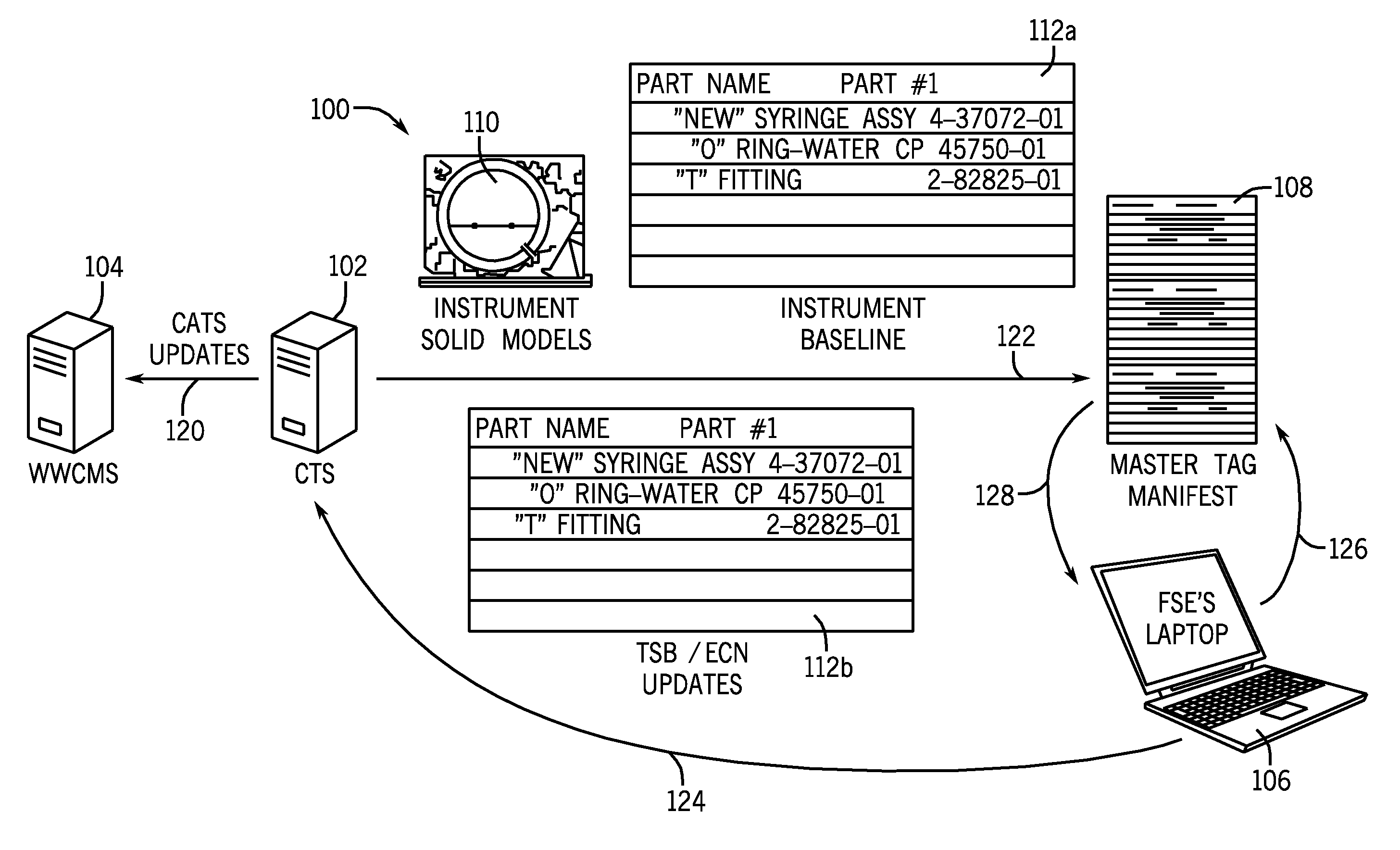
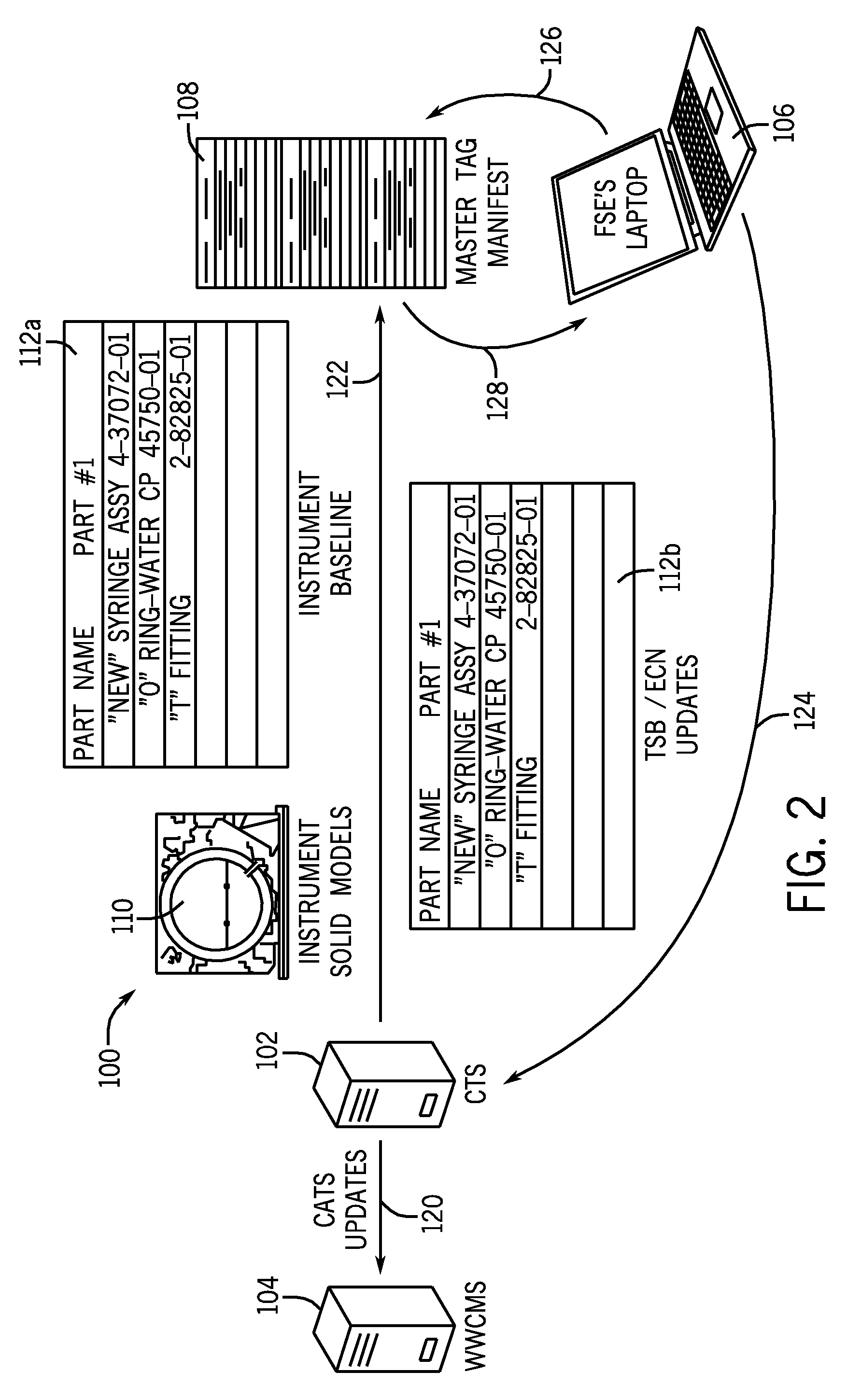
A system and method for the tracking of medical instrument, components, assemblies, and sub-assemblies thereof, and maintenance information relating to the foregoing. According to the system, radio frequency identification tags are attached to or affixed on the medical instrument itself for the purpose of locating, identifying, monitoring, tracking the medical instrument and updating the maintenance and replacement activities relating to the medical instrument. In addition, radio frequency identification tags are attached to or affixed on the components, the assemblies, and the sub-assemblies, of the medical instrument in order to locate, identify, monitor, track the components, the assemblies, and the sub-assemblies and update the maintenance and replacement activities relating to these components, assemblies, and sub-assemblies. The medical instrument itself can have a radio frequency identification tag; each major component of the automated diagnostic instrument can have a radio frequency identification tag; each minor component of the automated diagnostic instrument can have a radio frequency identification tag on the container in which it is packaged. A master radio frequency identification tag correlated with a database is needed in order to collect information relating to all of the radio frequency identification tags associated with the medical instrument.

Description

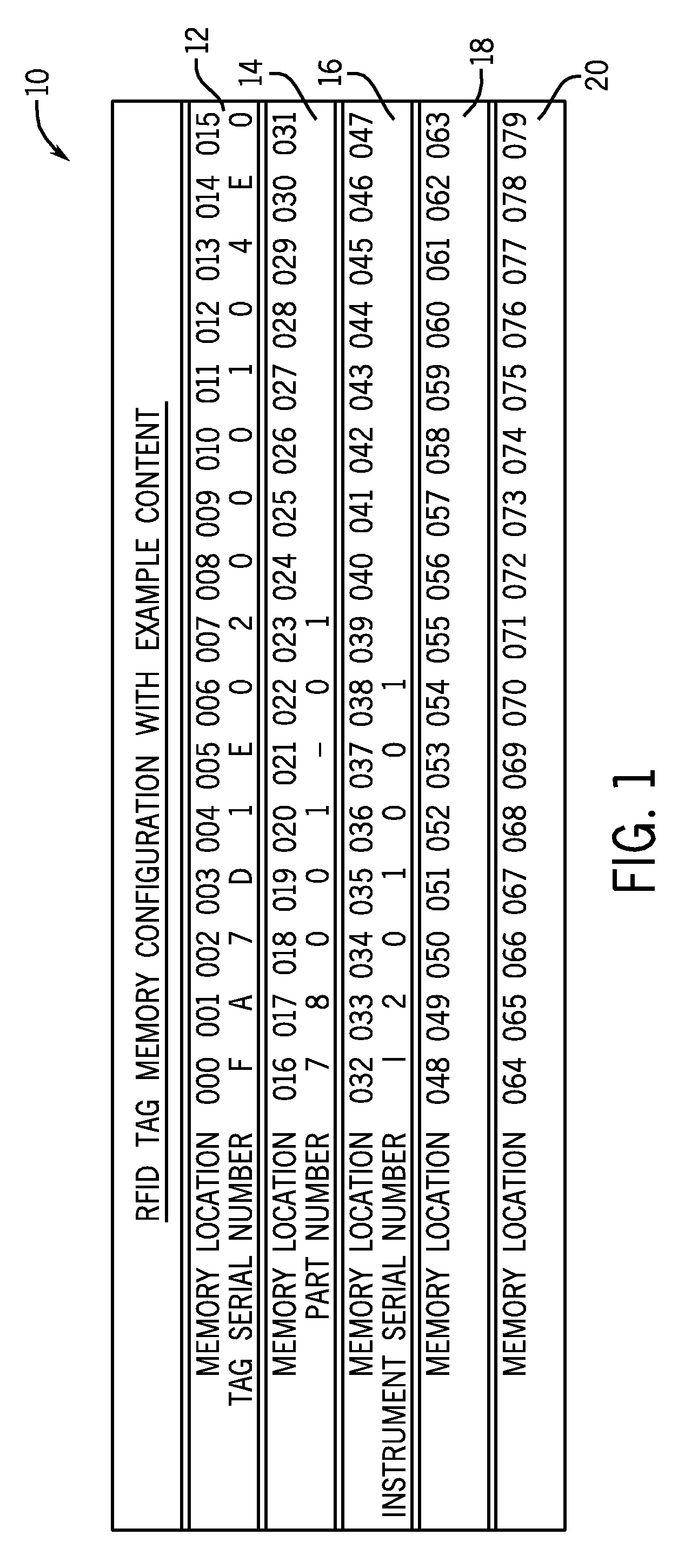
BACKGROUND OF THE INVENTION[0001]1. Field of the Invention[0002]This invention relates to tracking systems, more particularly, tracking systems for determining the location of components, assemblies, and sub-assemblies in medical instruments.[0003]2. Discussion of the Art[0004]Radio frequency identification (RFID) technology is an identification technology, which is capable of being automated, in which data are written to and data are read from tags that contain a microchip and an antenna by means of radio frequency signals. Radio frequency identification technology allows an active transmitter to selectively interrogate radio frequency identification tags attached to items of interest and capture the data transmitted from these radio frequency identification tags.[0005]There are several methods for storing identification information in radio frequency identification systems, but the most common method involves storing a serial number that identifies a person or object, and other in...

Claims


Application Information

Patent Timeline
Patent Type & Authority Patents(United States)
IPC IPC(8): G08B13/14
CPCA61B19/44G06F19/3412A61B2019/448G06K2017/0045A61B2019/4857A61B90/90A61B90/98A61B2090/0811G16H40/40
Inventor FRITCHIE, PATRICK P.SCHWARTZ, OSCAR F.LOPEZ, RENEE A.
Owner ABBOTT LAB INC
Why Eureka
Try Eureka