
Azimuthal equidistant projection navigation display and method

a technology of equidistant projection and navigation display, applied in the field of navigation display, can solve the problems of difficult safe and precise navigation

Active Publication Date: 2011-04-26
HONEYWELL INT INC
View PDF3 Cites 5 Cited by
  • Summary
  • Abstract
  • Description
  • Claims
  • Application Information

AI Technical Summary

Problems solved by technology

This relative location error can make safe and precise navigation more difficult.
While the above noted distortion problem associated with flat navigational displays applies to any type of moving vehicle (e.g., car, ship, plane, etc.) or observer therein, they are more apparent with aircraft because of the aircraft's relatively high speed.

Method used


Image

  • Azimuthal equidistant projection navigation display and method
  • Azimuthal equidistant projection navigation display and method
  • Azimuthal equidistant projection navigation display and method

Examples


Embodiment Construction

[0016]The following detailed description of the invention is merely exemplary in nature and is not intended to limit the invention or the application and uses of the invention. Furthermore, there is no intention to be bound by any theory presented in the preceding background of the invention or the following detailed description of the invention.

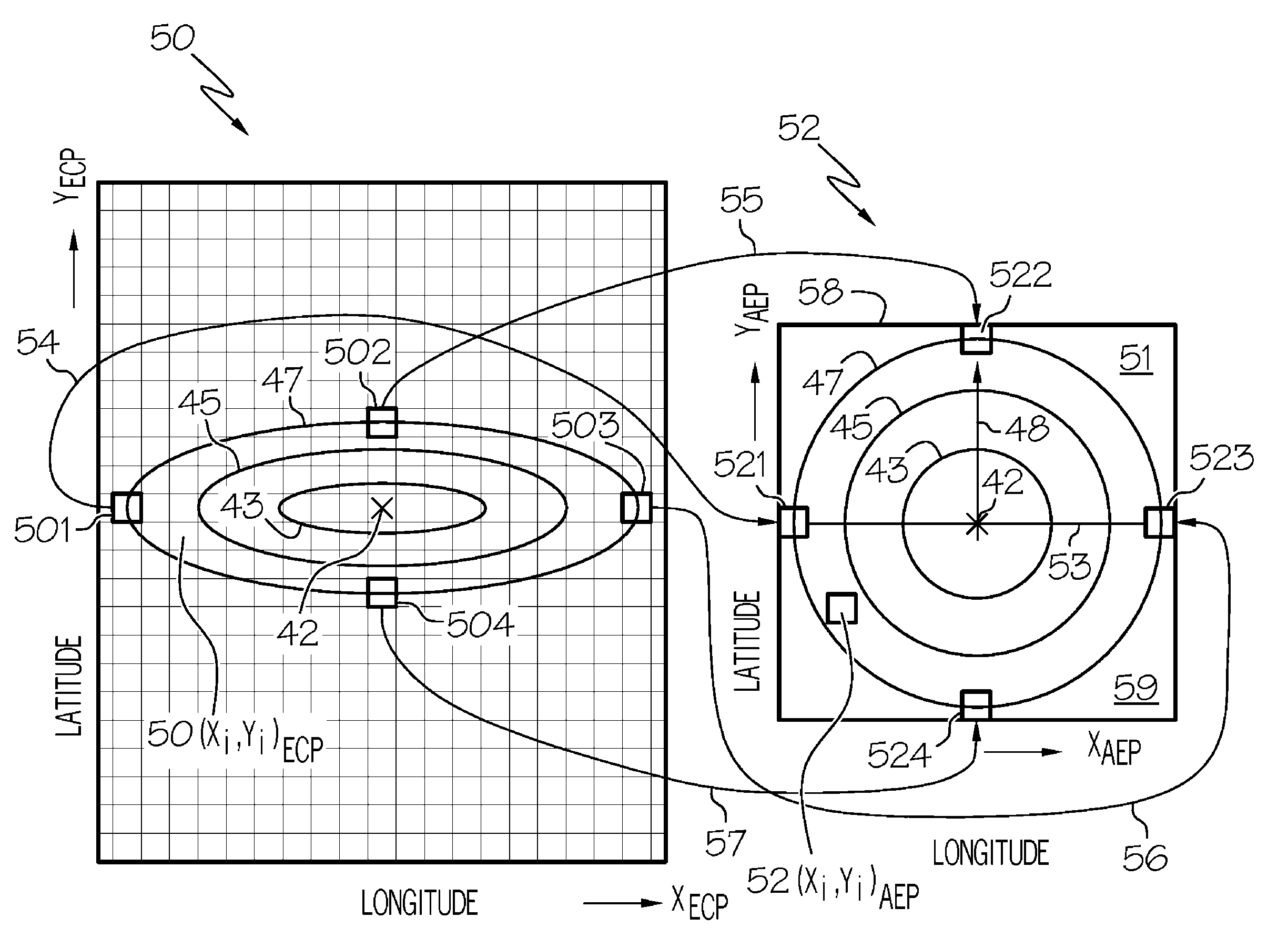
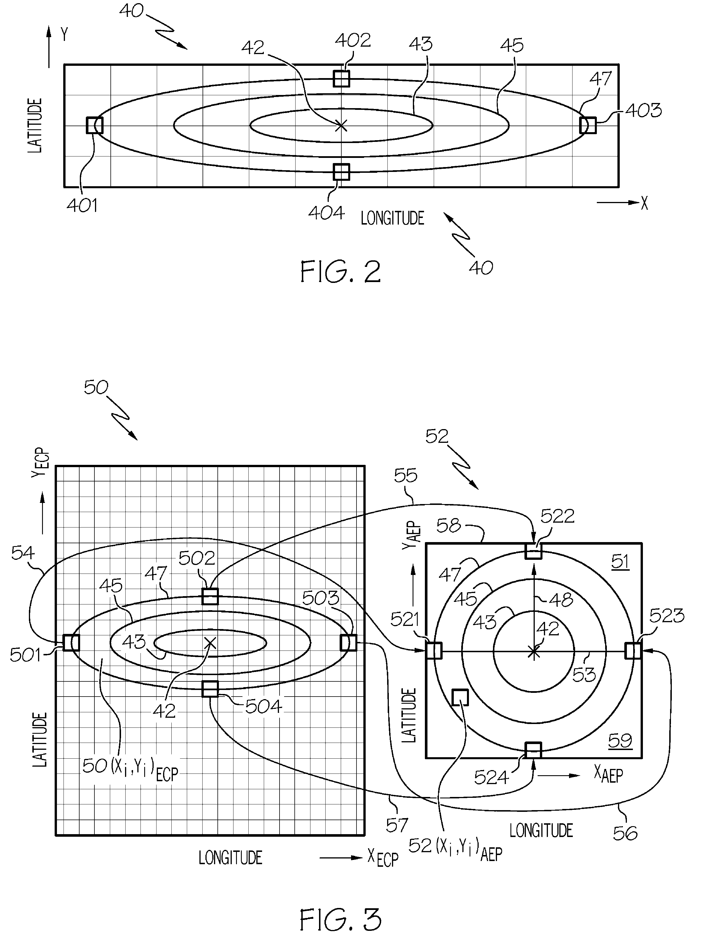
[0017]FIG. 2 illustrates graphically a region of interest of two-dimensional ECP map data 40 such as that shown in FIG. 1 for a particular region of earth. It is assumed for purposes of explanation that an aircraft is located at position 42 and that contours 43, 45 and 47 represent different radii from the aircraft as measured on the surface of the earth. Contours 43, 45 and 47 need not be regular or concentric as viewed from ECP map data 40. They are completely dependent on the underlying source ECP map data 40 and are defined simply by each (Φ,λ) coordinate along their curves. FIG. 3 shows graphical method 49 illustrating how texture data ...


PUM


Abstract

Methods and apparatus are provided for an azimuthal equidistant projection (AEP) aircraft navigational display. The apparatus comprises a generator providing the aircraft's current latitude and longitude (φ1,λ0), a user input for providing the desired map radius R, a display for presenting the navigational information, a map data source providing topographical information associated with geo-spatial coordinates, and a controller and memory coupled to the generator, data source, input and display for providing data transformations. Map data containing topographical information associated with each geo-spatial coordinate is obtained from the map data source for an area of approximately radius R from (φ1,λ0). Using the controller and memory, the geo-spatial coordinates are converted to AEP spatial coordinates so that the topographical information is now associated with such AEP spatial coordinates. The transformed map data is sent to the display to provide AEP navigational information on the display around (φ1,λ0).

Description

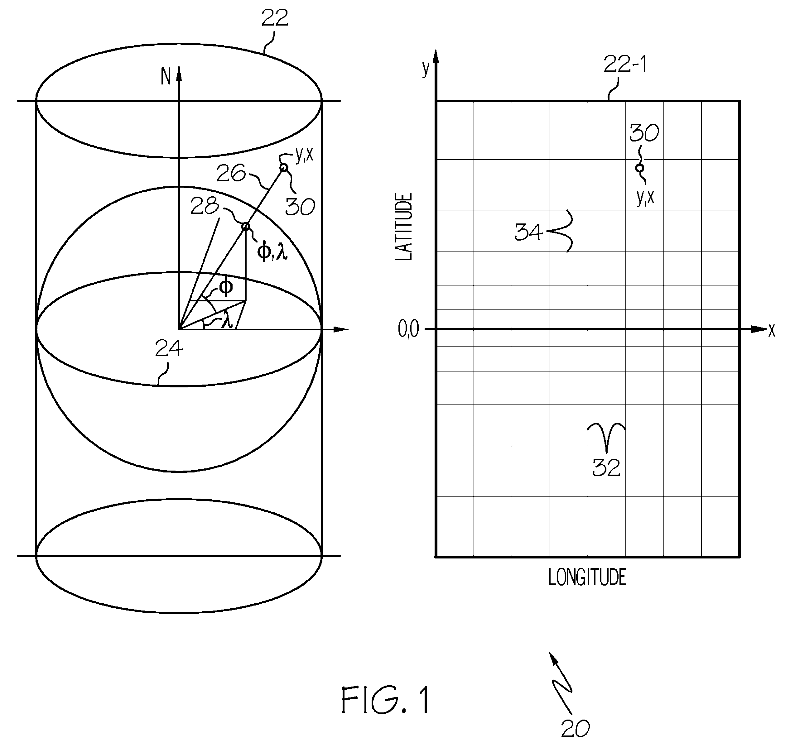
FIELD OF THE INVENTION[0001]The present invention generally relates to navigation displays and more particularly relates to aircraft navigation displays providing current aircraft location relative to features on a map of the surrounding area.BACKGROUND OF THE INVENTION[0002]It is common today to provide navigational map displays of the landscape or seascape over which a vehicle is passing, with the vehicle's current position indicated thereon. These displays are almost always flat, which requires that the curved surface of the earth be presented in two dimensions rather than its actual three dimensions. The curvature of the earth is not ignored, rather the curved surface of the earth is projected onto a two-dimensional plane and that projection is what is presented on the display.[0003]FIG. 1 illustrates graphically method 20 of generating two dimensional equidistant cylindrical map projection (ECP) 22 of a spherical surface (e.g., the three dimensional earth's surface) 24 and the ...

Claims


Application Information

Patent Timeline
Patent Type & Authority Patents(United States)
IPC IPC(8): G01S5/00
CPCG01C21/00G01C21/387
Inventor DROPPS, TIMOTHY C.MEEKER, JOHNROFF, MARKRONISH, EDWARD W.
Owner HONEYWELL INT INC
Learn More