Supercharge Your Innovation With Domain-Expert AI Agents!

Combustor turbine interface

a technology of turbine interface and compressor, which is applied in the direction of machines/engines, stators, lighting and heating apparatus, etc., can solve the problems of reducing the cooling effectiveness of the cooling air, affecting the cooling and core gas flow, and affecting the cooling effect of the cooling air

Inactive Publication Date: 2011-05-03
RTX CORP
View PDF25 Cites 9 Cited by
  • Summary
  • Abstract
  • Description
  • Claims
  • Application Information

AI Technical Summary

Benefits of technology

[0007]The example combustor assembly according to this invention includes a combustor liner assembly incorporating a heat shield article having an aft segment or lip corresponding to a fixed vane portion of a turbine assembly to form a smooth interface for gas flow. The aft segment or lip extends an axial distance greater than the remainder of the combustor assembly (and underlying shell) into the endwall region of the downstream fixed vane. The fixed vane endwall includes a landing that receives the aft lip such that the portions of the lip and endwall exposed to the core flow provide a smooth curvature in moving axially. The smooth axial profile provided by the lip and landing provide the desired aerodynamic properties for the cooling and gas flow at the transition between the combustor and the turbine endwalls. Moreover, the geometry of the landing is configured to tailor cooling patterns and limited unwanted cooling air leakage in this region.
[0008]Accordingly a combustor assembly according to this invention provides for the smooth transition of cooling and core flow gas streams from the combustor assembly through the fixed vanes and into the downstream turbine hardware.

Problems solved by technology

Disadvantageously, such interrupted surfaces at the interface between the fixed vane array and the combustor interfere with cooling and core gas flows exiting the combustor.
The insulating layer of cooling air along the inner surface of the combustor is disrupted by the interface with the fixed vane portion causing undesirable mixing of the cooling air with the hot core gases.
This can lead to decreases in the cooling effectiveness of the cooling air and promote elevated temperatures or adverse temperature gradients on the combustor and turbine hardware in this region.
Additionally, disruption of the gas flow that moves downstream into the fixed vane causes undesirable aerodynamic properties and thermal profiles that can potentially degrade the downstream turbine and, hence, overall engine performance.

Method used


Image

  • Combustor turbine interface
  • Combustor turbine interface
  • Combustor turbine interface

Examples


Embodiment Construction

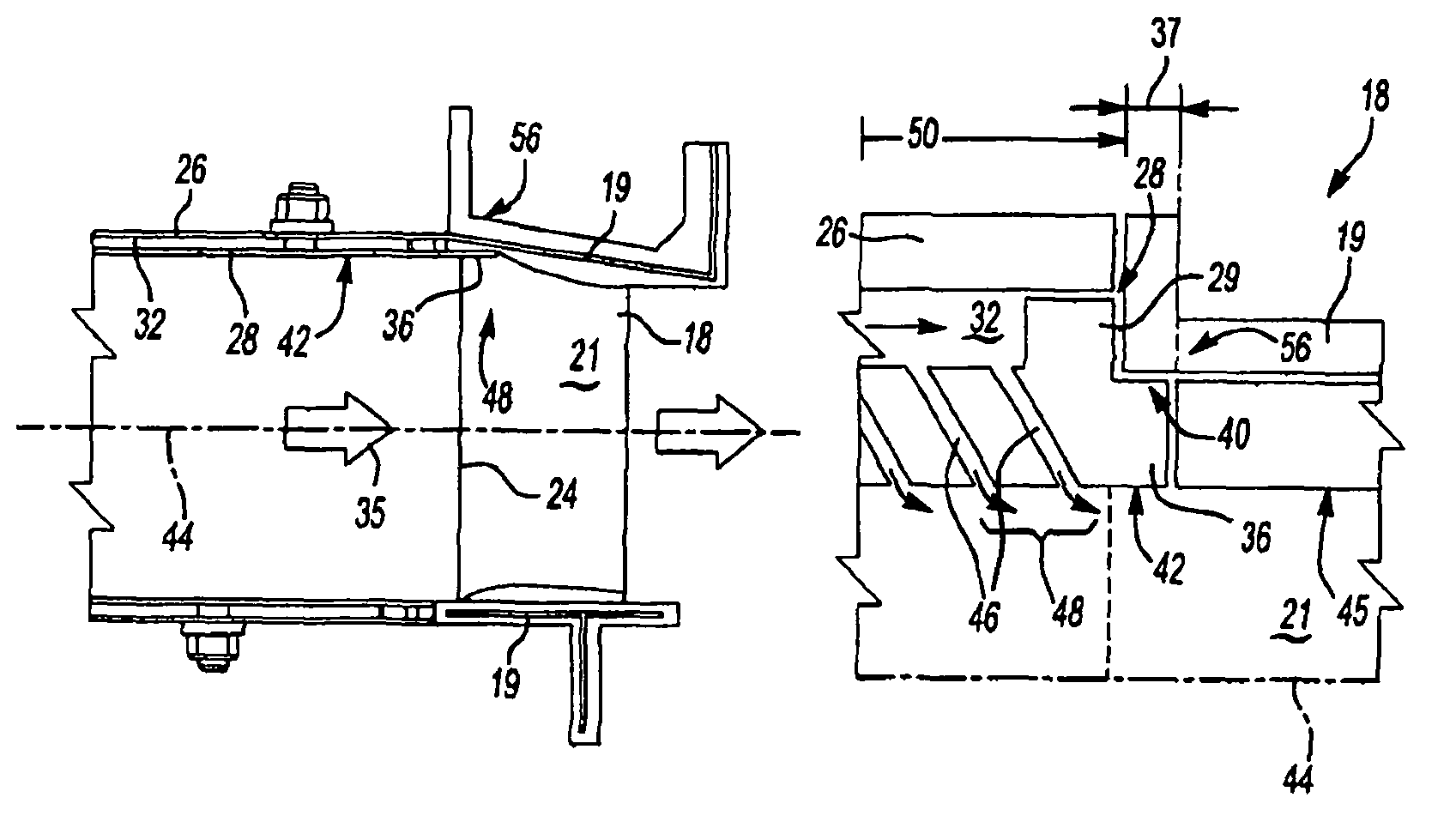
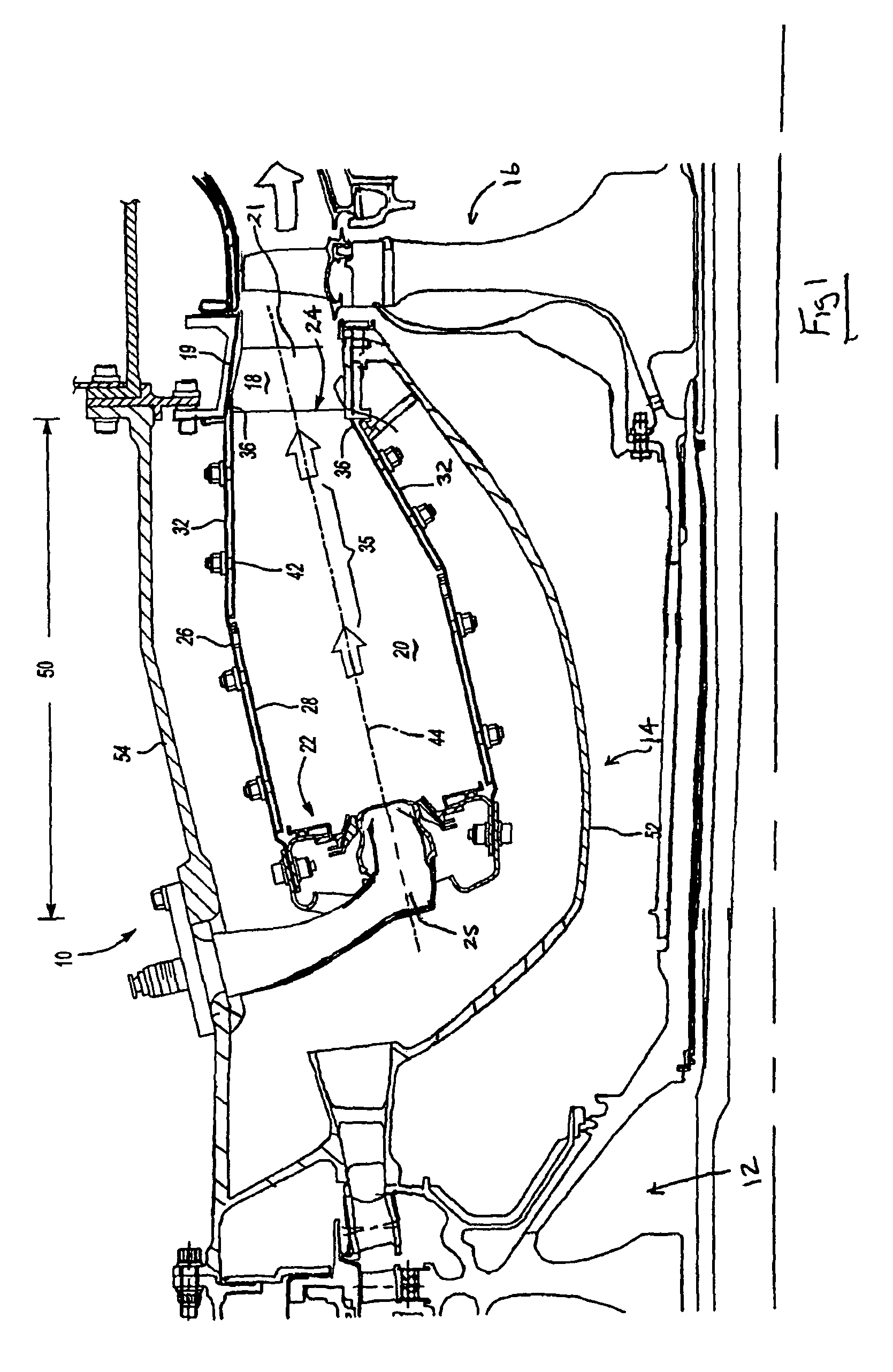
[0017]Referring to FIG. 1, an engine assembly 10 according to this invention includes a fan (not shown), a compressor 12 that supplies compressed air to a combustor assembly 14. Combustion gasses generated within the combustor assembly 14 flows into a turbine assembly 16. The gas turbine engine assembly 10 is shown schematically and illustrates an annular combustor although it is within the contemplation of this invention for application in other known combustor assembly configurations.

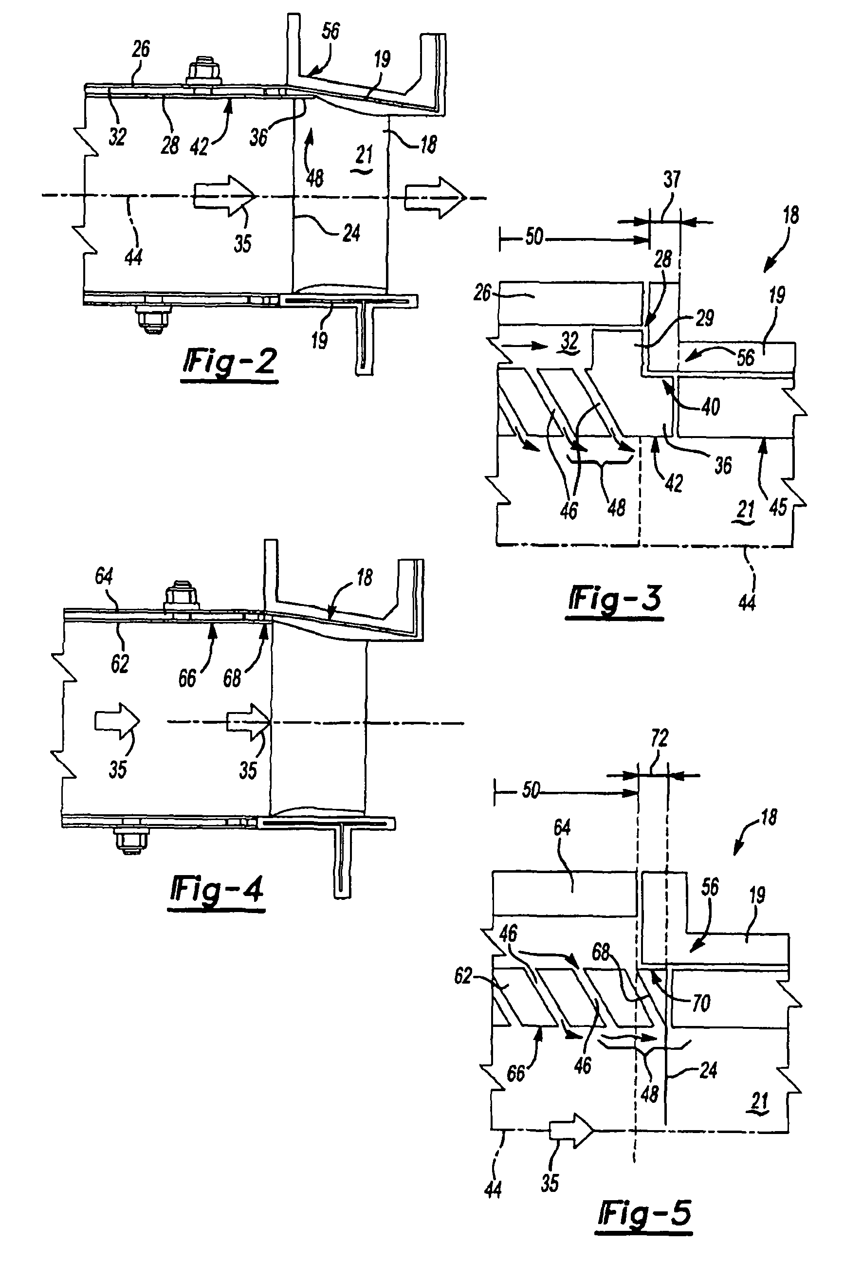
[0018]The combustor assembly 14 is disposed annularly about an axis 30 and includes an axial length 50. The combustor assembly 14 is secured within an inner (diffuser) case wall 52 and an outer (diffuser) case wall 54, each annularly disposed about the axis 30. The combustor assembly features a liner assembly 15 that is supported within the inner case wall 52 and outer case wall 54. The liner assembly 15 includes an outer shell 26 supporting a plurality of inner heat shields 28 that define an inner su...


PUM


Abstract

A combustor assembly for a turbine engine includes an aft open end that communicates gas flow to a turbine assembly. The combustor assembly includes a liner assembly that terminates at a first fixed vane. A portion of the liner assembly extends an axial distance into the first fixed vane portion. An inner surface of the liner assembly corresponds with inner surfaces of the fixed vane portion to provide a smooth transition from the inner surfaces of the combustor assembly to the turbine assembly.

Description

BACKGROUND OF THE INVENTION[0001]This invention relates generally to a combustor assembly for a gas turbine engine. More particularly, this invention relates to an interface between a combustor assembly and a fixed turbine vane portion of a gas turbine engine.[0002]A gas turbine engine typically includes a combustor for igniting a mixture of fuel and compressed air to produce a gas flow. The combustor typically includes an outer shell supporting a plurality of inner heat shields. The inner heat shields are exposed to elevated temperatures produced by ignition of the fuel-air mixture and the resulting gas flow.[0003]Gas flow exiting the combustor enters a fixed array of turbine vanes that directs gas flow to downstream rotating turbine blades. The fixed vanes are intermediate the combustor and the rotating turbine blades. Typically, the support shell and heat shield articles at the aft end of the combustor module terminate at a common axial position or plane upstream of the fixed van...

Claims


Application Information

Patent Timeline
Patent Type & Authority Patents(United States)
IPC IPC(8): F02C1/00
CPCF01D9/023F23R3/50F05D2240/35
Inventor BURD, STEVEN W.
Owner RTX CORP
Features
  • R&D
  • Intellectual Property
  • Life Sciences
  • Materials
  • Tech Scout
  • Unparalleled Data Quality
  • Higher Quality Content
  • 60% Fewer Hallucinations
Learn More