Gyroscopic exerciser

a gyroscopic exerciser and gyroscopic technology, applied in gymnastic exercise, engine components, muscle operated starters, etc., can solve the problems of limiting the application of conventional gyroscopic exercisers to the hand and its proximal muscle regions rather than the whole body, unable to allow multiple muscle groups of the body to be exercised simultaneously, and overwhelming attachments for customizing, etc., to achieve quiet and smooth operation of exercise devices and reduce idle weight of exercise devices

Active Publication Date: 2011-05-03
SMITH TOM
View PDF8 Cites 15 Cited by
  • Summary
  • Abstract
  • Description
  • Claims
  • Application Information

AI Technical Summary

Benefits of technology

[0020]A ring-shaped frame assembly surrounds the housing and has an outer ring member with an annular flange and a smaller inner ring member received in the flange of the outer ring member and fastened thereto, both ring members having opposing annular recesses for cooperatively holding the top and bottom halves of the racetrack of the gyroscopic movement unit. And a pair of truss members fastens the handles to the frame assembly at two diametrically opposite locations from the inner and outer ring members. Each of the inner and outer ring members further has multiple circumferential indentations diametrically positioned for reducing the idle weight of the exercise device. In one or more indentations there may be formed oil inlets communicating with the racetrack for lubricating the inside of the gyroscopic movement unit in order to provide a quiet and smooth operation of the exercise device.

Problems solved by technology

However, conventional gyroscopic exercisers too have limited applications to hand and its proximal muscle regions rather than the whole body.
Although this device can be used on any limb of the body or the torso, it does not permit several muscle groups of the body to be exercised simultaneously.
But the attachments for customizing are overwhelming and might need a substantial space to have them all together let alone keeping them portable.
All these efforts came short of providing an able gyroscopic exerciser that can be actually used to enhance limb exertions and performances of different muscles of the user's body (e.g., back muscles, deltoids, pectorals, biceps, and triceps).
Previously, the prior art had gyroscopic exercisers that were either difficult to start because of the complicated glitchy and underpowered electrical apparatus required to start it, or conversely the gyroscopic exercisers that were easy to start were low powered and lightweight compared to the heavier ones.
The rewind type rope starter of the prior art as shown in P. E. Mack has previously been overly bulky for use in gyroscopic applications.

Method used


Image

  • Gyroscopic exerciser
  • Gyroscopic exerciser
  • Gyroscopic exerciser

Examples


first embodiment

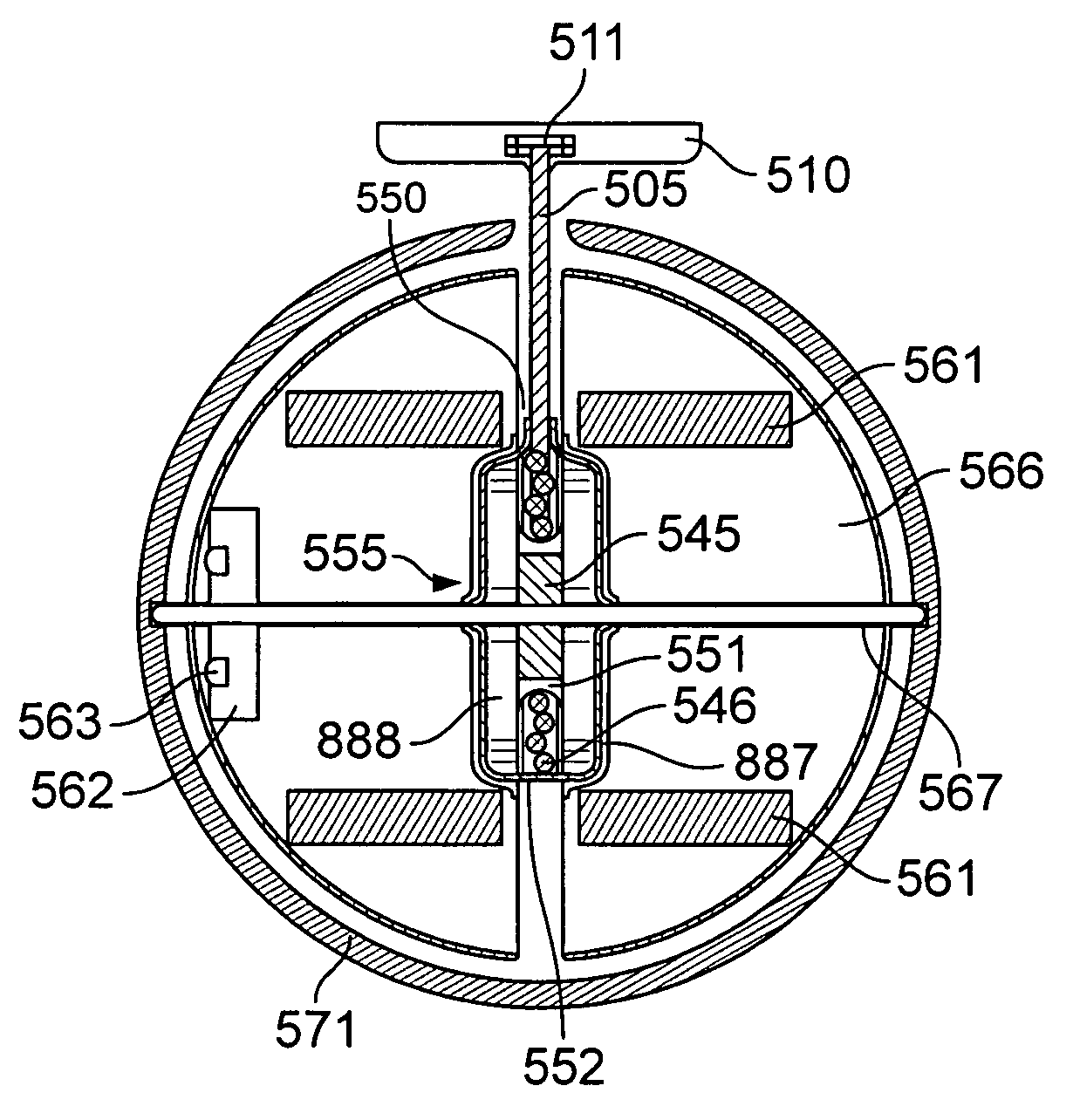
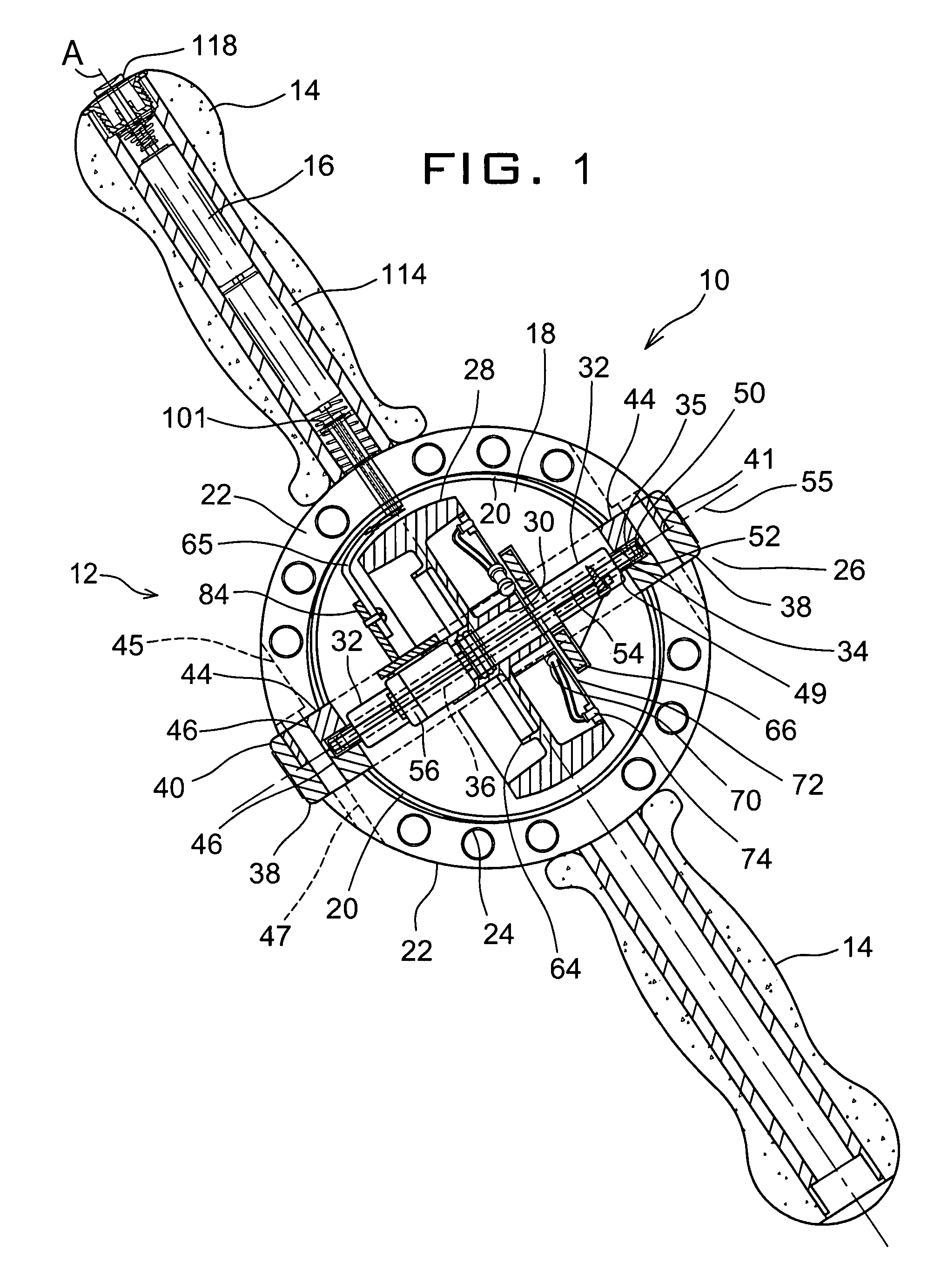
[0180]For the sake of drawing placement, FIG. 1 shows a gyroscopic exercise device 10 of the present invention oriented obliquely instead of normal horizontal position assumed during use thereof. The device 10 somewhat resembles a motorcycle handlebar including a central gyro sphere 12 and two diametrical handles 14 extending along a common axis A, which is concentric to the axis of precession and in turn the axis of uniquely dynamic and graceful body movements of the exerciser. One or both of the handles 14 may hold two AA-size batteries 16 inside to initialize the activation of the gyro sphere 12, which comprises a transparent or semi-transparent housing 18 for safely isolating the spinning components inside from the touch of a user but allowing the person a clear view of the operating status of the device 10.

[0181]The housing 18 may be divided into two identical semispherical shells 20 to which the handles 14 are attached through two suspension arches 22, respectively. Considerin...

second embodiment

[0193]As in FIG. 5 showing the present invention, the hinge means 58 may be integral to the conductor members 84 comprising two superimposed contacts 86, which are made from a conductive metal but insulated from each other by a thin layer of plastic sheath or coating 88. The top one of the contacts 86 is exposed and is provided with an opening 90 while the bottom one of contacts 86 is solid and isolated from the top contact due to the sheath 88. Middle portions of the contact 86 are screw fastened to the arm 82. Although not shown, by having a metal screw 92 first pass a tight hole in the bottom contact and then an enlarged slot in the top contact before it is driven through the arm 82, an unintentional short circuit may be prevented between the contacts 86.

[0194]The lower extremities of the conductor members 84 may be shaped into pivot arms 92 that extend along a common axis and are kept isolated. At the same time, a pair of partially sheathed high gauge (thick) wires 94 may be wel...

fourth embodiment

[0223]FIGS. 9 and 10 show sides of the exerciser of the invention having a manual pull starter 301 with a built-in secure device for storage in the exerciser handle 14. The pull starter 301 is identical to the starter 201 except that it also has a solid stop 348 that is threaded to mate with an inward thread 349 formed at an inner handle tip 320 of each of the opposite handles 14. For storage of the exerciser 200, the pull starter 301 may be readily placed in the exerciser from either handle 14 and screwed thereto for holding the total exerciser 200 onto a secure hanger or opening.

[0224]To start the exerciser 200, one may release the pull starter 301 first and make the movement of pulling start by holding a starter handle 340. The manual pull starter 301 is preferably stiff yet flexible and resilient enough so that a user can get the rotor up to preferably at least 4000 revolutions per minute on the first pull.


PUM


Abstract

A gyroscopic exercise device has a pair of handles attached to a housing. A user holds and rotates the handles along cone-like paths causing precession of a rotor, which is rotating about its spin axis, to provide resistance to the user. The device has an axle disc that holds ends of an axle of the rotor. The periphery of the axle disc and the ends of the rotor axle are within a circular race in the housing. A retracting spool allows pull starting. An optional motor attached to the axle disc has a wheel for rotating the rotor about a spin axis by a temporary supply of power from included batteries in one of the handles. An optional abdominal rolling ring provides abdominal exercise.

Description

[0001]This application is a continuation in part of and claims priority from Gyroscopic Total Exerciser filed Feb. 28, 2008 as U.S. patent application Ser. No. 12 / 072,776 now U.S. Pat. No. 7,563,210, which claims priority from provisional application for Smith, Tom 60 / 920,250 entitled Gyroscopic Total Exerciser filed Mar. 27, 2007.BACKGROUND OF THE INVENTION[0002]A. Field of the Invention[0003]The present invention relates generally to exercise devices and, in particular, to a gyroscopic device for a holistic physical exercise which is structured to accommodate either a sophisticated electrical motor-driven starter or a hand-pull starter to gain sufficient precession speed.[0004]B. Description of the Prior Art[0005]Gyroscopic exercisers have been known and developed in the hopes to provide dynamic physical exercises. For example, firefighters must often exert their forearms and wrists, as do most competitive athletes. In daily life, people rely on strong muscles in every task from l...

Claims


Application Information

Patent Timeline
Patent Type & Authority Patents(United States)
IPC IPC(8): A63B21/22
CPCA63B21/0004A63B21/22F02N3/02A63B2021/222A63B23/12A63B21/222A63B23/03525A63B21/4043
Inventor SMITH, TOM
Owner SMITH TOM
Why Eureka
Try Eureka