
Special rail trolley for friction rolling on rail

A track car and track technology, applied in conveyor control devices, conveyor objects, conveyors, etc., can solve problems such as reduced efficiency, high motor power, and unfavorable production line expansion and transformation.

Inactive Publication Date: 2021-07-06
安徽艾灵科工业科技有限公司
View PDF0 Cites 1 Cited by
  • Summary
  • Abstract
  • Description
  • Claims
  • Application Information

AI Technical Summary

Problems solved by technology

[0002] The traditional conveyor line device drives the motor to run with the entire conveyor line. The power of the motor is large, which is a waste of electric energy. When the tray has signal processing or needs to be moved with electricity, it needs to be equipped with a cable drag chain to protect the cable, so it cannot be carried out for a long time. Distance transportation is not conducive to the expansion and transformation of production lines
The traditional conveyor system uses chains, synchronous belts or belts, which need to be tightened. As the temperature changes in seasons, the tension needs to be adjusted. If the tension is not proper, it will also affect the effect of the conveyor line. As a result, track transportation has become more and more popular. However, the pallets on the trolley need to be stopped when the products are transported, and the positioning needs to use a jacking mechanism. The structure is complex and cumbersome, which is not conducive to cost reduction and efficiency improvement.

Method used

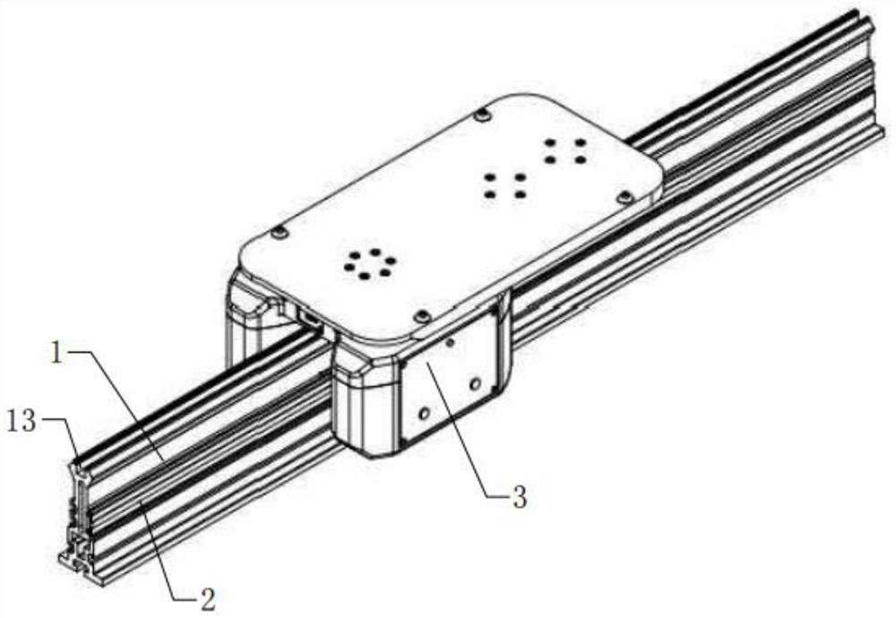
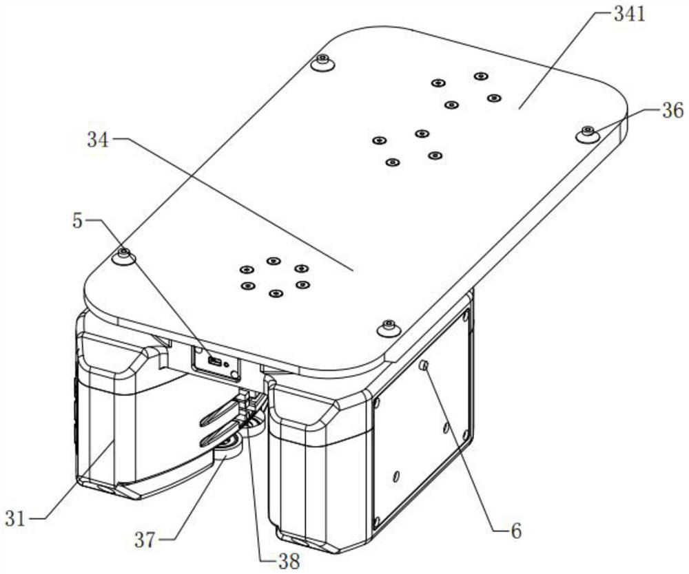
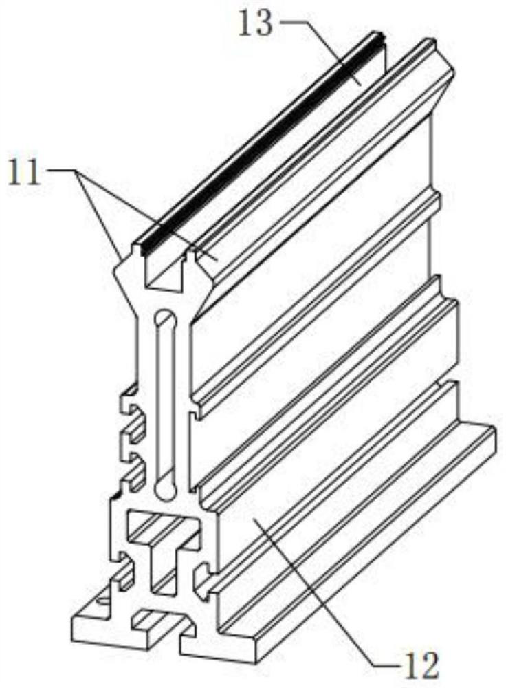

Image

  • Special rail trolley for friction rolling on rail
  • Special rail trolley for friction rolling on rail
  • Special rail trolley for friction rolling on rail

Examples


Embodiment Construction

[0027] The preferred embodiments of the present invention will be described in detail below in conjunction with the accompanying drawings, so that the advantages and features of the present invention can be more easily understood by those skilled in the art, so as to define the protection scope of the present invention more clearly.

[0028] It should be noted that when an element is referred to as being “fixed on” or “disposed on” another element, it may be directly on the other element or there may be an intervening element at the same time. When an element is referred to as being "connected to" another element, it can be directly connected to the other element or intervening elements may also be present.

[0029] In addition, it should be noted that the orientation terms such as left, right, up, and down in the embodiments of the present invention are only relative concepts or refer to the normal use state of the product, and should not be considered as limiting sexual. Th...


PUM


Abstract

The invention discloses a special rail trolley for friction rolling on a rail. Two opposite inclined surfaces are arranged at the top of the rail; the upper ends of the two inclined surfaces are close to each other; the lower ends of the two inclined surfaces are far away from each other; a copper strip is arranged on the rail in the length direction; the rail trolley comprises a trolley body; a motor and an even number of inclined surface rollers are arranged in the trolley body; the inclined surface rollers are uniformly distributed on the two sides of the rail and are respectively propped against the two inclined surfaces; the motor drives the inclined surface rollers to roll along the inclined surfaces; an electric brush in contact with the copper strip is arranged on the trolley body; the electric brush is used for supplying power to the motor; a tail plate is arranged on the top surface of the trolley body; the tail plate comprises an extension portion which extends in the same direction or the opposite direction of the running direction of the trolley body; and an even number of supporting rollers are arranged below the extension portion. The rail trolley is driven to move through the friction force between the inclined surface rollers and the inclined surfaces, so that the rail trolley runs more quietly and stably, and the processing requirement is low.

Description

technical field [0001] The invention relates to the technical field of conveying equipment in industrial automation, in particular to a special track trolley that frictionally rolls on a track. Background technique [0002] The traditional conveyor line device drives the motor to run with the entire conveyor line. The power of the motor is large, which is a waste of electric energy. When the tray has signal processing or needs to be moved with electricity, it needs to be equipped with a cable drag chain to protect the cable, so it cannot be carried out for a long time. Distance transportation is not conducive to the expansion and transformation of production lines. The traditional conveyor system uses chains, synchronous belts or belts, which need to be tightened. As the temperature changes in seasons, the tension needs to be adjusted. If the tension is not proper, it will also affect the effect of the conveyor line. As a result, track transportation has become more and more...

Claims


Application Information

Patent Timeline
Patent Type & Authority Applications(China)
IPC IPC(8): B65G35/00B65G43/00
CPCB65G35/00B65G43/00
Inventor 吴琼王爽潘永国
Owner 安徽艾灵科工业科技有限公司
Learn More