Self-balancing switched reluctance motor

A switched reluctance motor, self-balancing technology, applied in electrical components, electromechanical devices, etc., can solve problems such as high noise and vibration

Inactive Publication Date: 2016-11-23
韦翔
View PDF5 Cites 2 Cited by
  • Summary
  • Abstract
  • Description
  • Claims
  • Application Information

AI Technical Summary

Problems solved by technology

[0006] The purpose of the present invention is to provide a switched reluctance motor with self-balancing...

Method used


Image

  • Self-balancing switched reluctance motor
  • Self-balancing switched reluctance motor
  • Self-balancing switched reluctance motor

Examples


Embodiment Construction

[0014] The present invention will be further explained below in conjunction with the accompanying drawings.

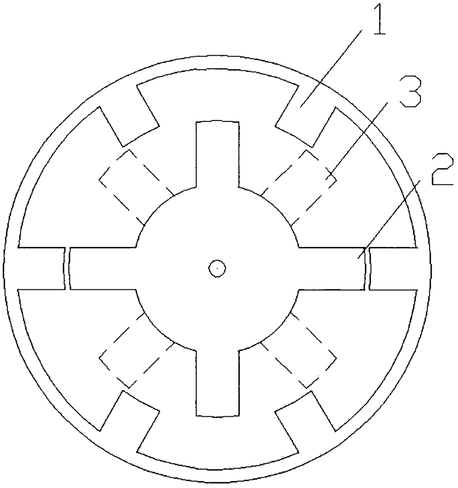
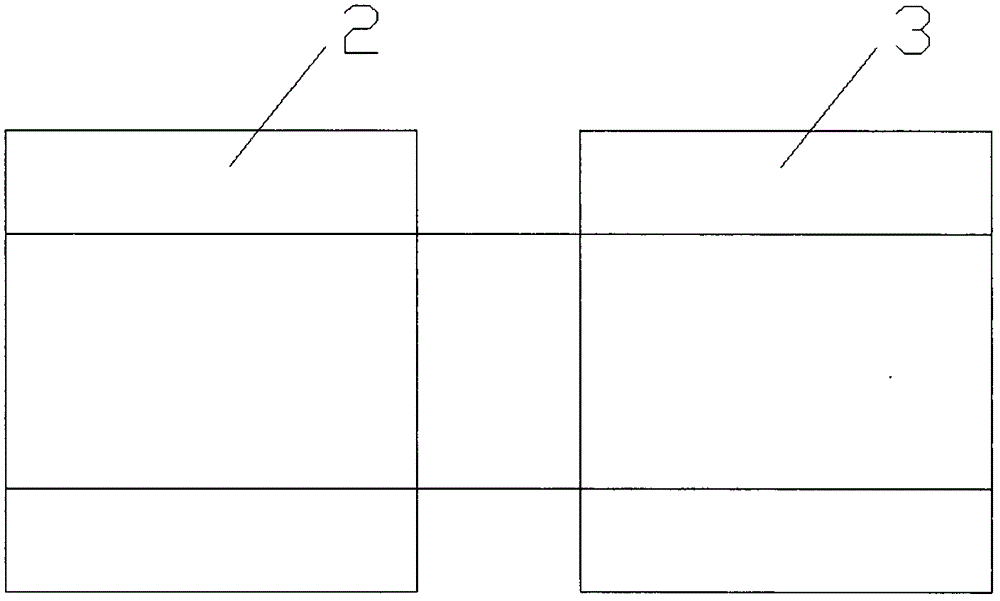
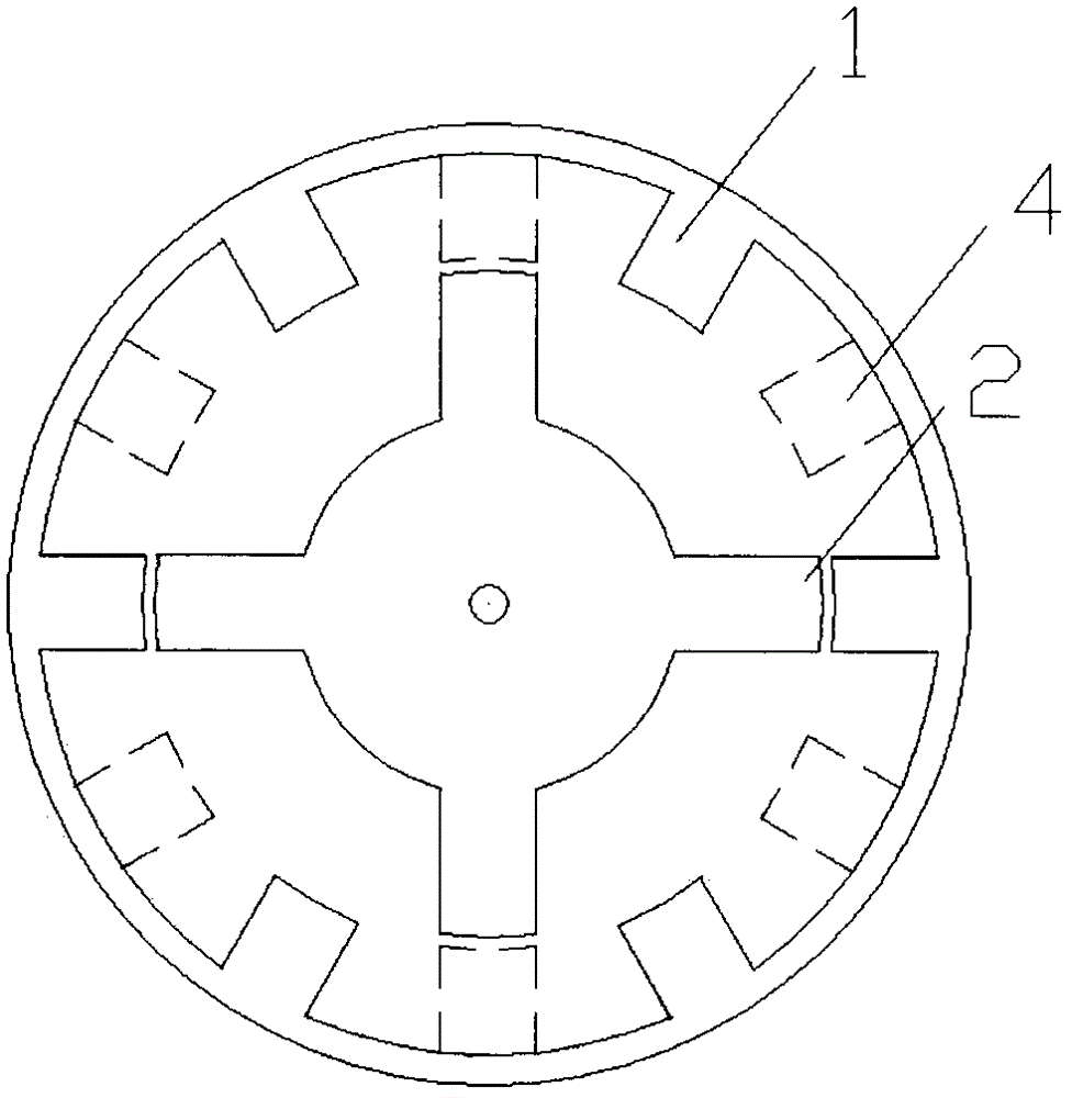
[0015] Such as figure 1 , figure 2 As shown, it is an embodiment of the present invention, the salient poles of the stator (1) are wrapped with coils, the rotor (2) and the rotor (3) are coaxially connected and separated by a certain distance, the rotor (2) and the rotor ( 3) The salient poles are staggered by 30°. A magnetic field is generated by controlling the on-off coil current on each pair of salient poles of the stator (1), and the rotor (2) and the rotor (3) are respectively driven by the magnetic field to rotate according to the principle of minimum reluctance. During the working process, the working state of the rotor (2) and the rotor (3) is just opposite. When the torque of the rotor (2) is the largest, the torque of the rotor (3) is just the minimum; when the torque of the rotor (2) is the minimum, the torque of the rotor (3) is just The torque is the ...


PUM


Abstract

The invention relates to a switched reluctance motor which overcomes the shortcomings of large pulsating torque and vibration and high noise of a current switched reluctance motor. A plurality of stators and a plurality of rotors are combined to form a plurality of switched reluctance sub-motors, a plurality of rotors share a rotating shaft to collectively output power, the switched reluctance sub-motors are mutually and serially connected, stators or rotors of each switched reluctance sub-motor are distributed according to a certain rule, the switched reluctance sub-motors are mutually balanced by the aid of pulsating torques of the switched reluctance sub-motors, and stable and quiet operation is achieved. As the switched reluctance sub-motors collectively output the power, and the self-balancing switched reluctance motor has the advantages of operational stability and quietness, stronger power and the like.

Description

technical field [0001] The invention relates to a novel switched reluctance motor, which belongs to electrical engineering. Background technique [0002] Switched reluctance motor is a new type of speed regulation motor. The speed regulation system has the advantages of both DC and AC speed regulation systems. It is the latest generation of stepless speed regulation system following the frequency conversion speed regulation system and brushless DC motor speed regulation system. It has simple and firm structure, wide speed regulation range, excellent speed regulation performance, high efficiency in the whole speed regulation range, and high system reliability. It is mainly composed of four parts: switched reluctance motor, power converter, controller and position detector. The controller contains the control circuit and the power converter, and the rotor position detector is installed at one end of the motor. [0003] The motor part is called a reluctance motor because it u...

Claims


Application Information

Patent Timeline
IPC IPC(8): H02K16/00
CPCH02K16/00
Inventor 韦翔
Owner 韦翔
Why Eureka
Try Eureka