Magnetically operated electrical switch

a technology of electrical switches and magnetic switches, applied in the direction of electric switches, magnetic movement switches, electrical apparatus, etc., can solve the problems of inherently less reliable than other switches, time-consuming and potentially expensive installation, and unauthorized use of machines or appliances

Inactive Publication Date: 2011-05-03
UNETLANVHI HLDG
View PDF22 Cites 12 Cited by
  • Summary
  • Abstract
  • Description
  • Claims
  • Application Information

AI Technical Summary

Problems solved by technology

These switches allow for unauthorized use of the machines or appliances that they control because these types of switches are generally unguarded.
Furthermore, wall switches and countertop mounted switches are typically time consuming and potentially expensive to install because the installation of these switches may require actions such as, but not limited to, cutting holes in sinks countertops and walls, connecting wires, and installing tubes.
Air switches have the added disadvantage of several additional required mechanical parts causing them to be inherently less reliable than other switches.

Method used


Image

  • Magnetically operated electrical switch
  • Magnetically operated electrical switch
  • Magnetically operated electrical switch

Examples


Embodiment Construction

[0018]The present invention is best understood by reference to the detailed figures and description set forth herein.

[0019]Embodiments of the invention are discussed below with reference to the Figures. However, those skilled in the art will readily appreciate that the detailed description given herein with respect to these figures is for explanatory purposes as the invention extends beyond these limited embodiments. For example, it should be appreciated that those skilled in the art will, in light of the teachings of present invention, recognized a multiplicity of alternate and suitable approaches, depending upon the needs of the particular application, to implement the functionality of any given detail described herein, beyond the particular implementation choices in the following embodiments described and shown. That is, there are numerous modifications and variations of the invention that are too numerous to be listed but that all fit within the scope of the invention. Also, sin...


PUM


Abstract

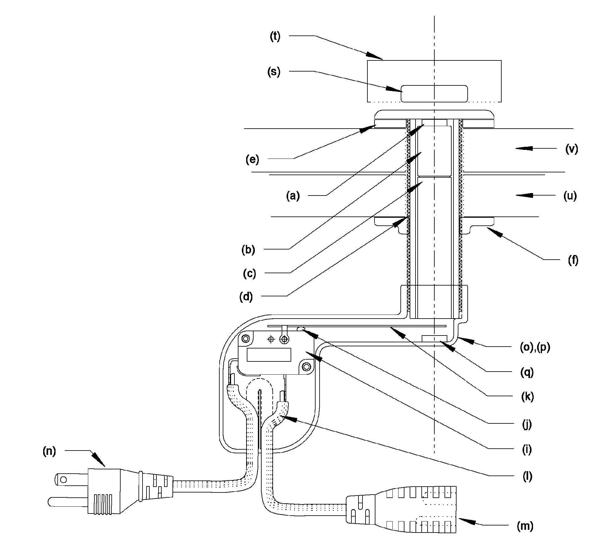
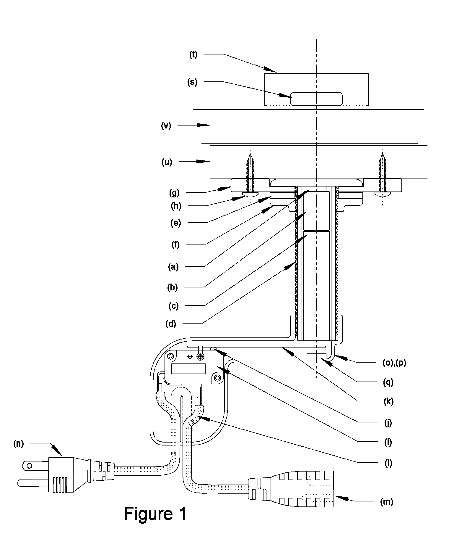
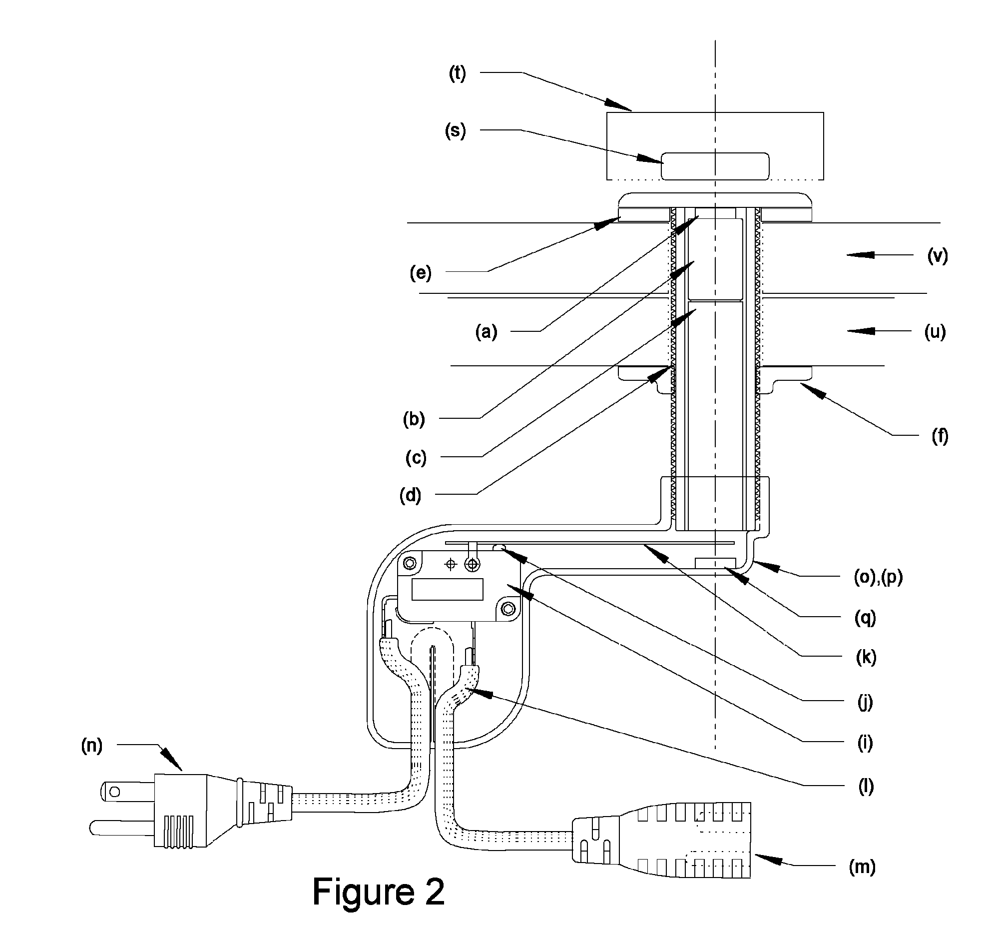
A magnetically operated electrical switch is presented. The electrical switch includes a linear magnet assembly contained within a housing and movable along an axis of the housing, a rod attached to an end of the linear magnet facing an open end, and means for attaching the housing to a surface. An electrical switch assembly attachable to the open end includes a make / break switch, a switch plunger and an operating lever engaging the plunger where the make / break switch is placed in the first position when an end of the operating lever is contacted by the rod. An electrical wire connection harness includes at least two conductors where the make / break switch closes / opens a connection between one of the conductors. When an operating magnet assembly is positioned on the surface proximate to the switch, the operating magnet moves the linear magnet and a position of the make / break switch is changed.

Description

FEDERALLY SPONSORED RESEARCH OR DEVELOPMENT[0001]Not applicable.REFERENCE TO SEQUENCE LISTING, A TABLE, OR A COMPUTER LISTING APPENDIX[0002]Not applicable.COPYRIGHT NOTICE[0003]A portion of the disclosure of this patent document contains material that is subject to copyright protection. The copyright owner has no objection to the facsimile reproduction by anyone of the patent document or patent disclosure as it appears in the Patent and Trademark Office, patent file or records, but otherwise reserves all copyright rights whatsoever.FIELD OF THE INVENTION[0004]The present invention relates generally to the control of electrical appliances and machines. More particularly, the invention relates to means for operating an electrical appliance or machine via the attractive force of a repositionable magnet as the operator or “key” and a fixed magnet or electrical switch assembly that opens and closes an electrical circuit.BACKGROUND OF THE INVENTION[0005]Typically, the operation of an appl...

Claims


Application Information

Patent Timeline
Patent Type & Authority Patents(United States)
IPC IPC(8): H01H9/00
CPCH01H36/0073H01H13/186
Inventor CARPENTER, WILLIAM N
Owner UNETLANVHI HLDG
Why Eureka
Try Eureka