Deformation of a computer-generated model

a computer-generated model and model technology, applied in the field of computer-generated model deformation, can solve the problems of increasing the size of the control mesh, difficult to approximate the implicit surface with a mesh, and limited control of surface modifications

Active Publication Date: 2011-05-03
DASSAULT SYST SOLIDWORKS CORP
View PDF26 Cites 45 Cited by
  • Summary
  • Abstract
  • Description
  • Claims
  • Application Information

AI Technical Summary

Problems solved by technology

Approximating an implicit surface with a mesh is generally difficult; however, methods have been developed to approximate an implicit surface.
The coarser the control mesh is, the more limited is the ability to control modifications to the surface.
However, a finer control mesh (which may be necessary to produce small features), increases the size of the control mesh, and therefore, requires more memory to store the surface and a greater number of computations to transform the surface.
One drawback of defining a space deformation is that deforming the space in which the surface is located is not intuitive because the objective is to deform the surface not the space in which the surface resides.
Reapproximating the result with a refinement of the original mesh often leads to a deterioration of the polygon aspect ratios.
Furthermore, if the space deformation is applied to a spline, converting the resulting surface back into a spline may be computationally costly and the smoothness of the surface may not be maintained.
Thus, manipulation controls are often restricted to particular points or curves of the surfaces.
The user, therefore, is limited in his or her ability to form a desired shape.
Achieving the desired accuracy of shape and smoothness between surface patches, in general, leads to high density control grids and makes such surfaces computationally expensive for subsequent operations.

Method used


Image

  • Deformation of a computer-generated model
  • Deformation of a computer-generated model
  • Deformation of a computer-generated model

Examples


Embodiment Construction

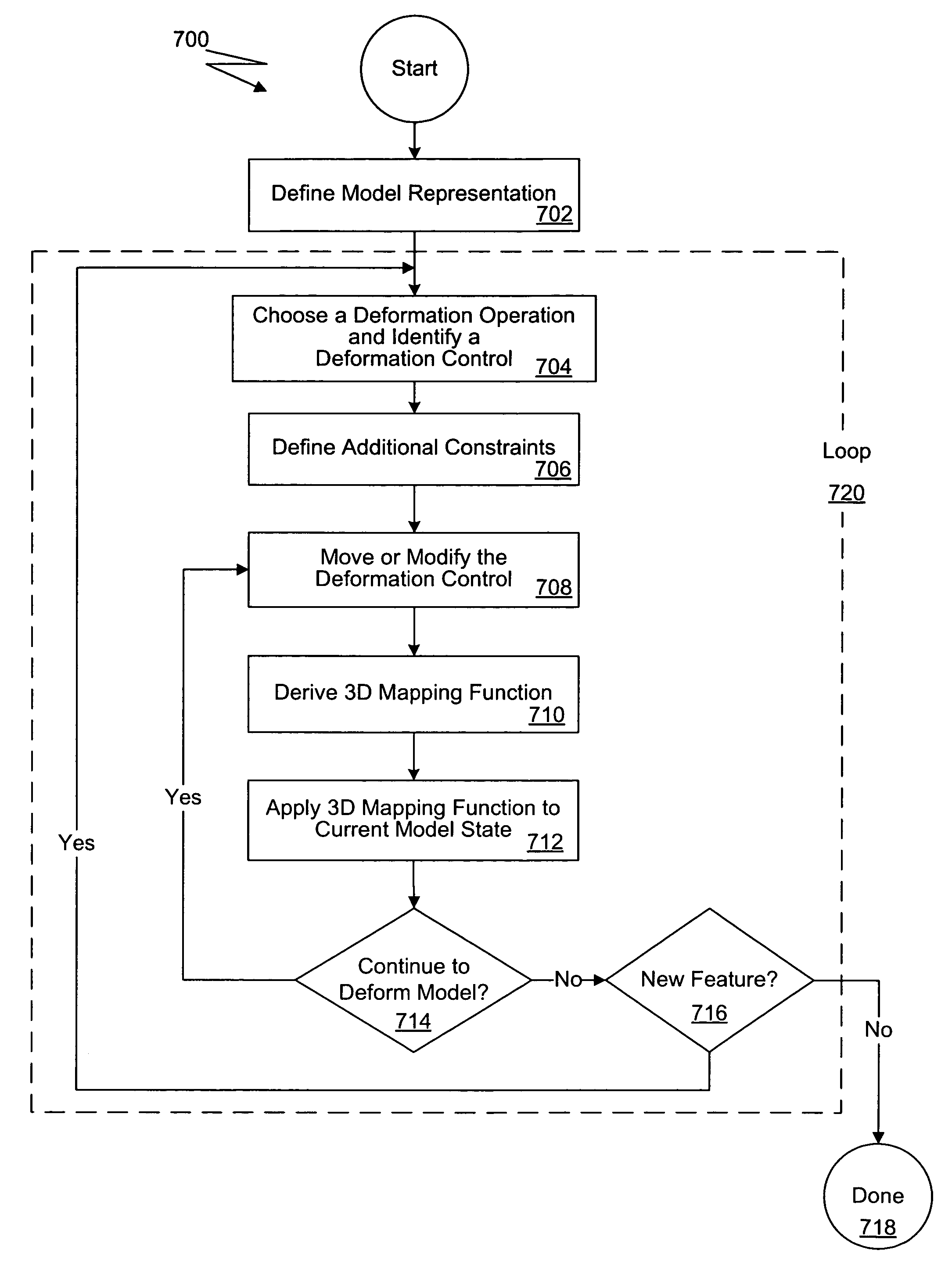
[0029]The present invention facilitates smooth real-time deformations of freeform surfaces by utilizing arbitrary lower-order geometry and other deformation controls to directly manipulate one or more surfaces. Such arbitrary lower-order geometry includes, by way of non-limiting example, points, curves, planes, axes, and surfaces. Moreover, the present invention preserves the existing smoothness of the surfaces and existing surface curvature characteristics. A sequence of smooth space mappings is used to change the shape of a model without a loss in model accuracy. Furthermore, a user interface provides users with a natural, fast, and simple approach to deforming freeform surfaces. The user interface affords access to a functional library that supports the direct interactive manipulation of one or more surfaces. Due to the foregoing, the present invention enhances the capabilities of a computerized modeling system.

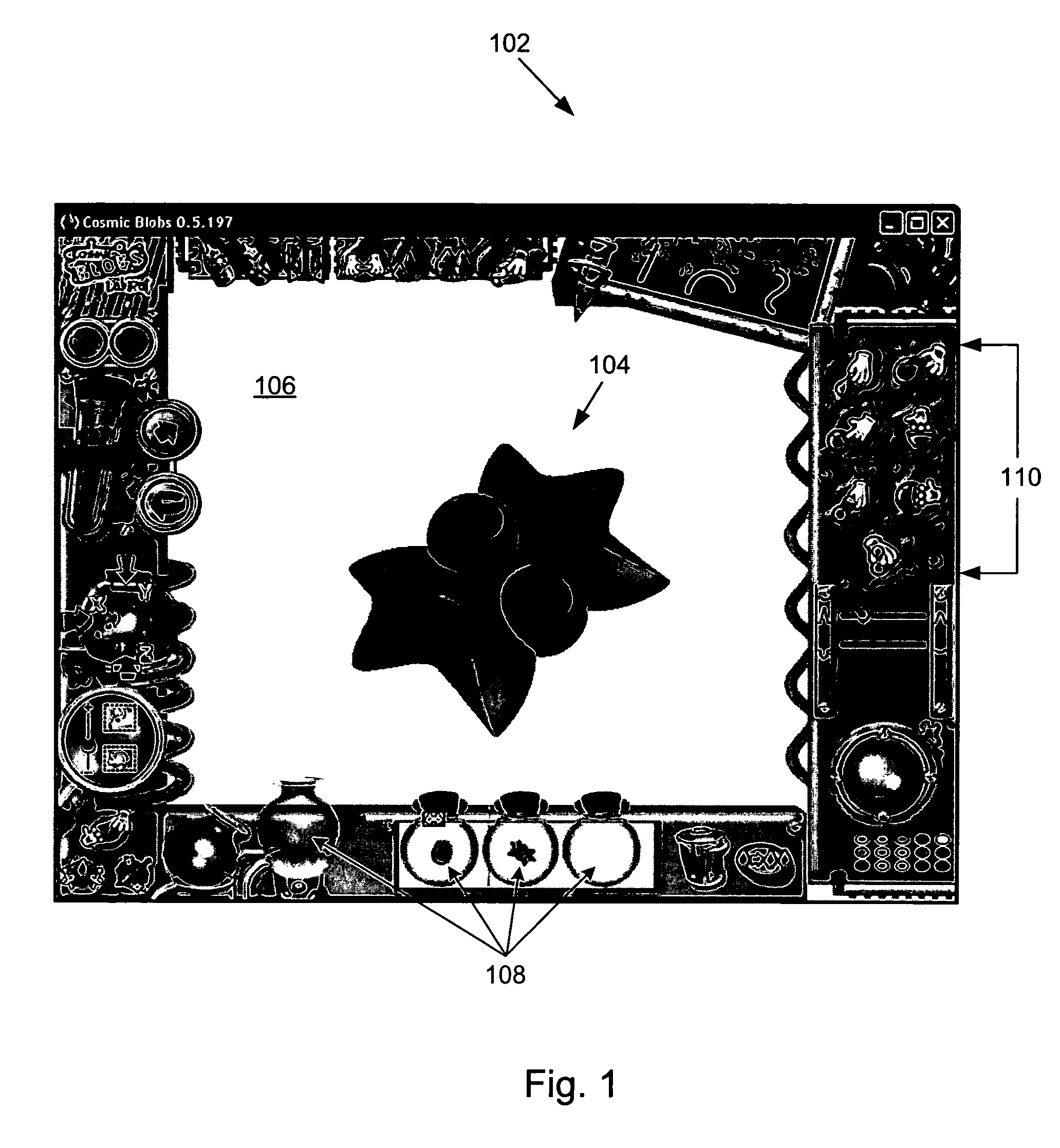
[0030]FIG. 1 shows a window 102 displayed on a CRT and generated by m...


PUM


Abstract

Deforming a three-dimensional computer-generated model to cause a change of shape of the three-dimensional model includes representing a surface of the model using a surface representation initially comprised of an original surface definition, deriving smooth three-dimensional mapping functions where each mapping function defines a deformation to the surface and at least one mapping function is non-affine, constructing a composition of the mapping functions and the original surface definition where each mapping function is included in the composition in succession in accordance with the order of derivation, and applying the composition after each successive mapping function is included in the composition causing the surface of the three-dimensional model to be deformed while preserving the smoothness to the lowest degree of smoothness of the mapping functions.

Description

BACKGROUND OF THE INVENTION[0001]Computer-aided design (CAD) software allows a user to construct and manipulate complex three-dimensional (3D) models. A number of different modeling techniques can be used to create a 3D model. These techniques include solid modeling, wire-frame modeling, and surface modeling. Solid modeling techniques provide for topological 3D models, where the 3D model is a collection of interconnected topological entities (e.g., vertices, edges, and faces). The topological entities have corresponding supporting geometrical entities (e.g., points, trimmed curves, and trimmed surfaces). The trimmed surfaces correspond to the topological faces bounded by the edges. Wire-frame modeling techniques, on the other hand, can be used to represent a model as a collection of simple 3D lines, whereas surface modeling can be used to represent a model as a collection of exterior surfaces. CAD systems may combine these and other modeling techniques, such as parametric modeling t...

Claims


Application Information

Patent Timeline
Patent Type & Authority Patents(United States)
IPC IPC(8): G06T17/00G09G5/00G06T15/30G06T17/40
CPCG06T17/30G06T19/20G06T2219/2021
Inventor BARAN, ILYAHARRIS, SCOTTSAKSONOV, LANAROTHSTEIN, SAULZUFFANTE, ROBERT
Owner DASSAULT SYST SOLIDWORKS CORP
Why Eureka
Try Eureka