Protective headgear

a headgear and protective technology, applied in the field of protective headgear, can solve the problems of not being practical for all players to wear cumbersome batting helmets, and the baseball player is still at risk of head injuries

Inactive Publication Date: 2011-05-10
NO PROBLEM
View PDF23 Cites 52 Cited by
  • Summary
  • Abstract
  • Description
  • Claims
  • Application Information

AI Technical Summary

Benefits of technology

[0005]It is a further object of the present invention to provide headgear, as above, which not only provides protection for the head but which is also padded so as to be comfortable to we

Problems solved by technology

However, the baseball player is still at risk of head injury while in the field, but it would n

Method used


Image

  • Protective headgear
  • Protective headgear
  • Protective headgear

Examples


Embodiment Construction

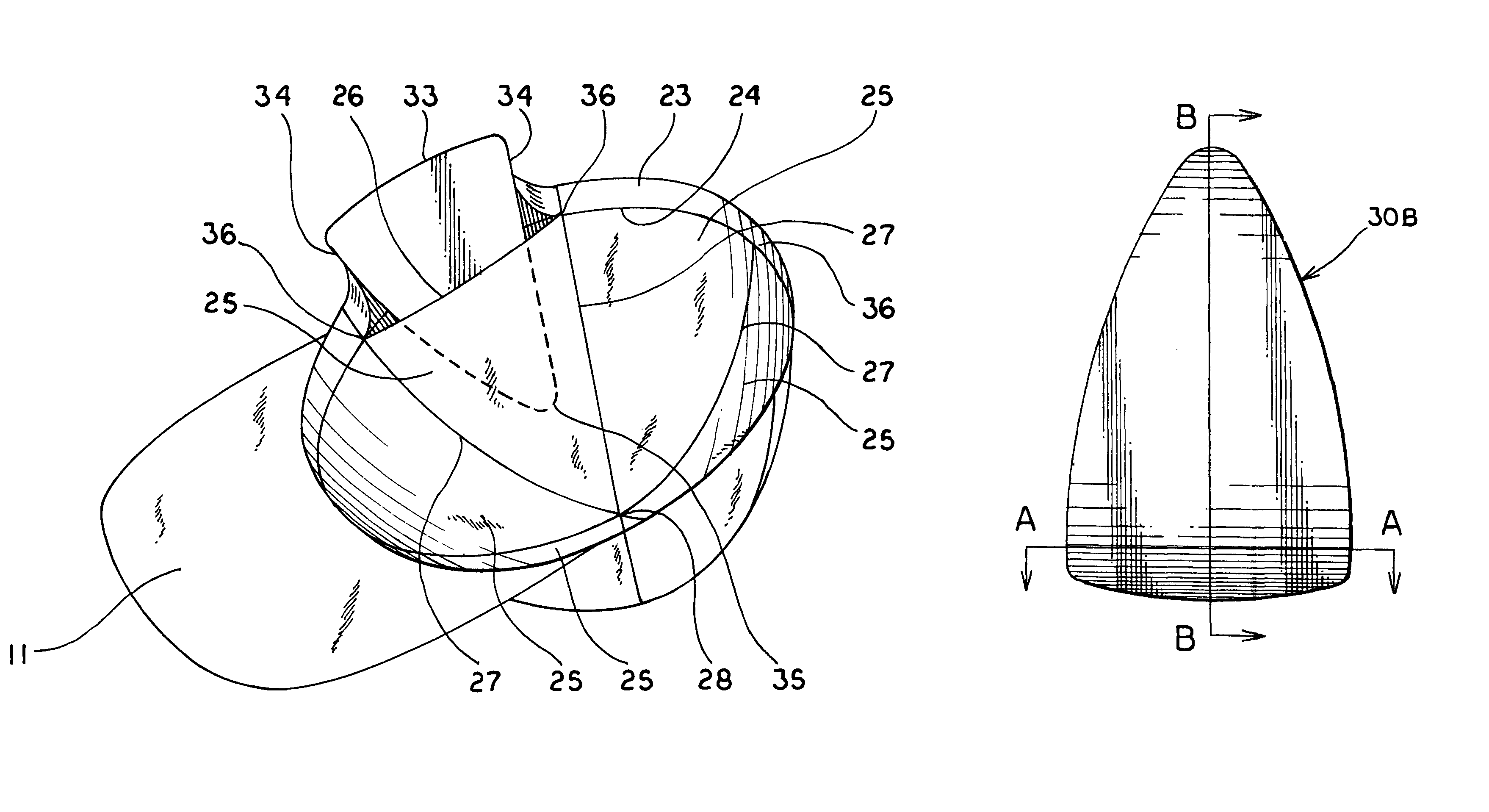
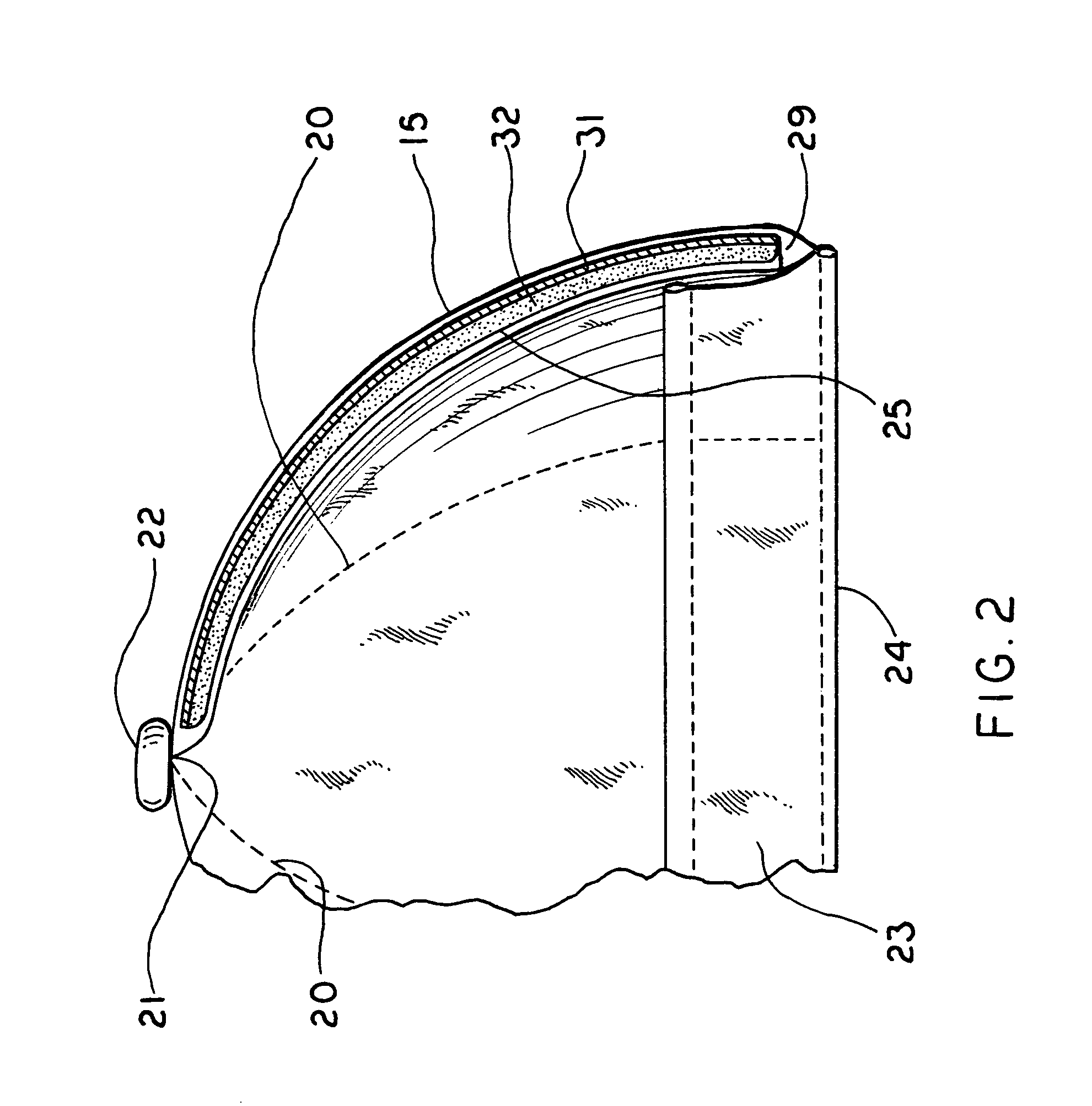
[0024]A protective headgear made in accordance with the present invention is shown in the configuration of a baseball cap and is generally indicated by the numeral 10. Cap 10 includes a conventional, fabric-covered, reinforced bill 11 and a head covering portion generally indicated by the numeral 12. Portion 12 is constructed of a plurality of fabric panels 13, 14, 15, 16, 17 and 18 each generally taking on the shape of an isosceles triangle having a base 19 and opposed sides 20 interconnected at a point 21 (FIG. 2). The sides 20 of adjacent panels 13-18, which may be slightly curved, are attached to each other, as by stitching or the like, and the points 21 of all panels 13-18 may be attached to each other as by a conventional button grommet 22 or the like. The bases 19 of all panels 13-18, which may also be slightly curved, may be attached to a headband 23 (FIG. 2) at the edge 24 thereof. The edge 24 of headband 23 is also attached to bill 11.

[0025]As best shown in FIG. 3, a piece...


PUM


Abstract

A cap (10) is provided with a plurality of pockets (29) formed between a plurality of panels (13-18) and fabric materials (25) attached to each of the panels (13-18). The pockets (29) have an open end which is covered by a headband (23). A protection segment (30) is positioned in each pocket (29) and includes a plastic protective panel (31) and an energy absorbing foam layer (32). The segments (30) are curved in both the longitudinal and lateral directions, but not all of the segments (30) have the same radii of curvature in those directions.

Description

TECHNICAL FIELD[0001]This invention relates to protective headgear such as might be worn by participants in a sporting event. More particularly, this invention relates to such headgear which takes on the appearance of a conventional cap but which is provided with padded reinforcement.BACKGROUND ART[0002]Protective headgear of various varieties are worn by participants in many different sporting events. For example, helmets are always worn by those participating in sports such as football and hockey, and a batting helmet is worn by a baseball player when batting or running the bases. These batting helmets can be sized to fit over an existing baseball cap, or can be worn directly on the head, but they are removed when the player takes the field for defensive purposes. However, the baseball player is still at risk of head injury while in the field, but it would not be practical for the cumbersome batting helmet to be worn by all players while in the field. Thus, the need exists for a p...

Claims


Application Information

Patent Timeline
IPC IPC(8): A42B3/00
CPCA42B1/08
Inventor NORTON, JOHN K.
Owner NO PROBLEM
Why Eureka
Try Eureka