Rekeyable lock cylinder and operating method thereof

a lock cylinder and key technology, applied in the field of lock cylinders, can solve problems such as security problems, and achieve the effect of enhancing the burglarproof of the rekeyable lock cylinder

Active Publication Date: 2011-05-10
TAIWAN FU HSING INDAL
View PDF17 Cites 21 Cited by
  • Summary
  • Abstract
  • Description
  • Claims
  • Application Information

AI Technical Summary

Benefits of technology

[0004]It is an object of the present invention to provide a rekeyable lock cylinder and operating method thereof. First, a first matched key is inserted into a keyhole of a plug body and turning the first matched key to drive the plug body and a position block rotating. Next, a programming tool is inserted into a first through hole of the plug body and a second through hole of the position block. Next, the programming tool is turned to push against a tool-contacting surface of the position block and make each of the first rack components move along the transverse axis-direction of the plug body to release engagement with each of the second rack components. Next, the first matched key is pulled out before inserting a second matched key into the keyhole. Finally, the programming tool is turned to reengage the first and second rack components thereby completing overall rekeying process. According to the present invention, the programming tool can contact against the tool-contacting surface of the position block during turning process to push against the position block and drive the first rack components releasing engagement with the second rack components. On the contrary, if the used tool cannot contact against the tool-contacting surface during turning process, the position block cannot be moved to rekey, therefore, the present invent has efficiency of enhancing burglarproof of the rekeyable lock cylinder.

Problems solved by technology

However, linkage mechanism of the foregoing lock cylinder lacks burglarproof in design when rekeying as well as the simple tool is easy to obtain, that might be subject to unauthorized rekeying operation resulting in security problem.

Method used


Image

  • Rekeyable lock cylinder and operating method thereof
  • Rekeyable lock cylinder and operating method thereof
  • Rekeyable lock cylinder and operating method thereof

Examples


Embodiment Construction

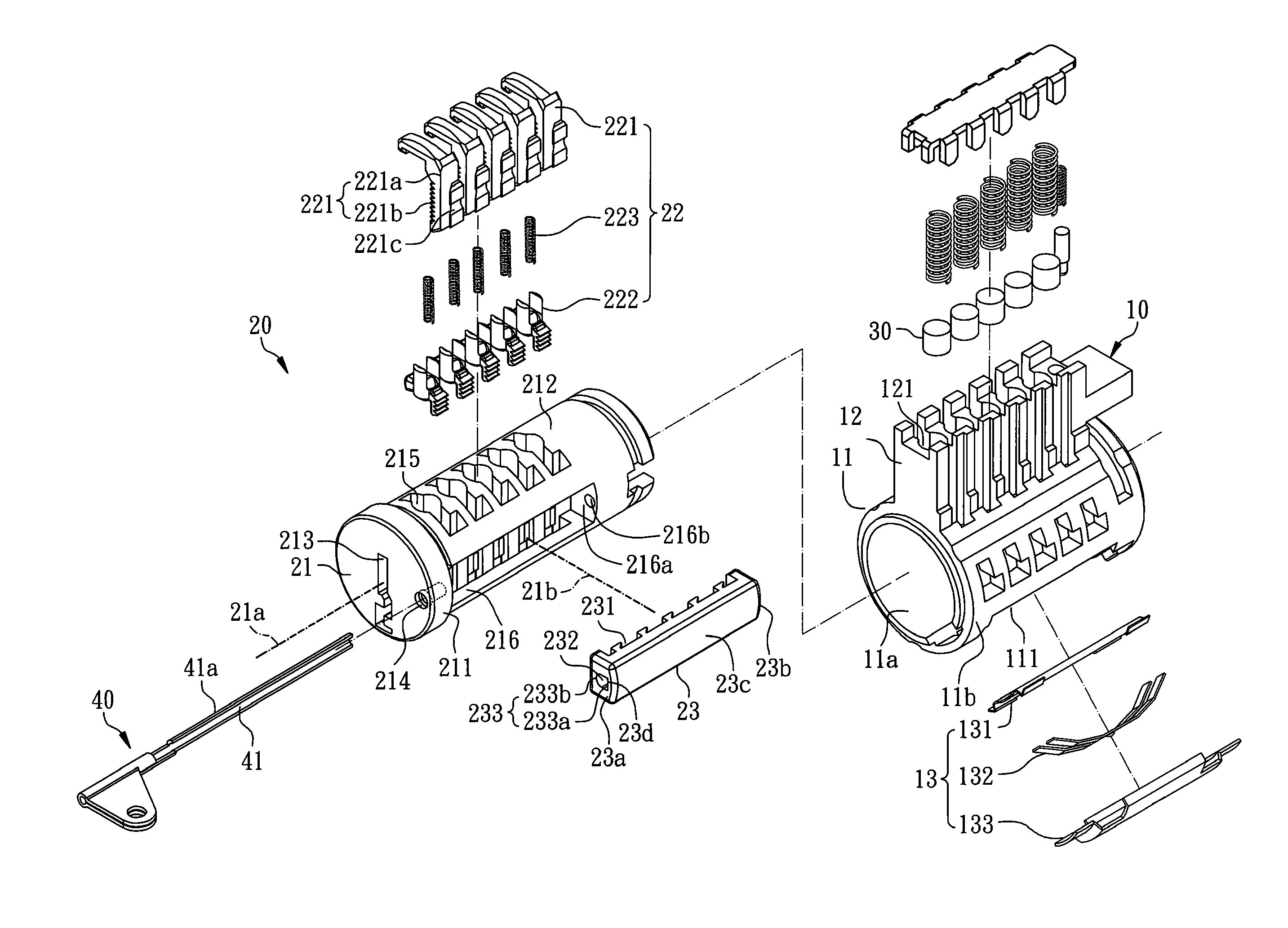
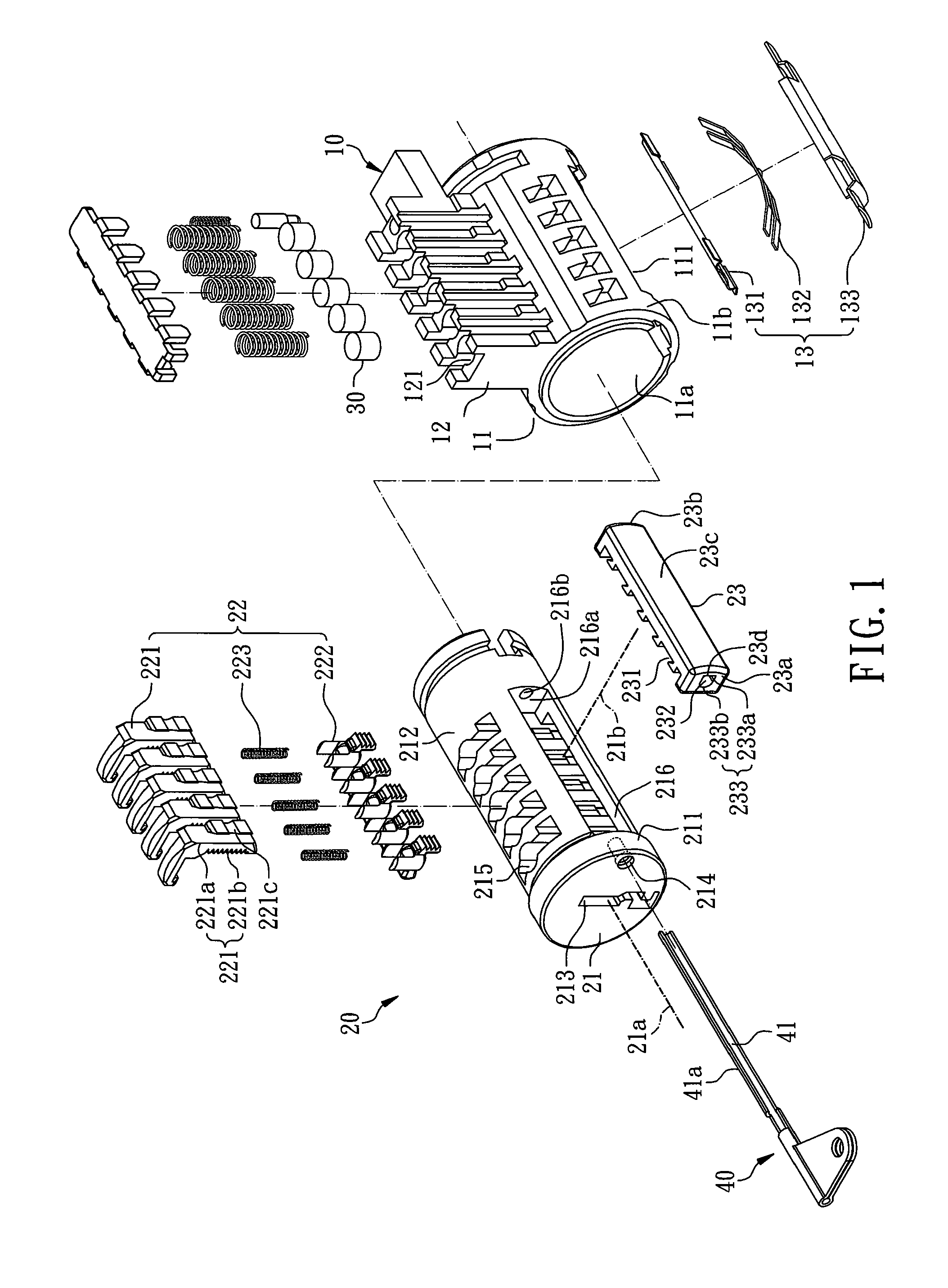
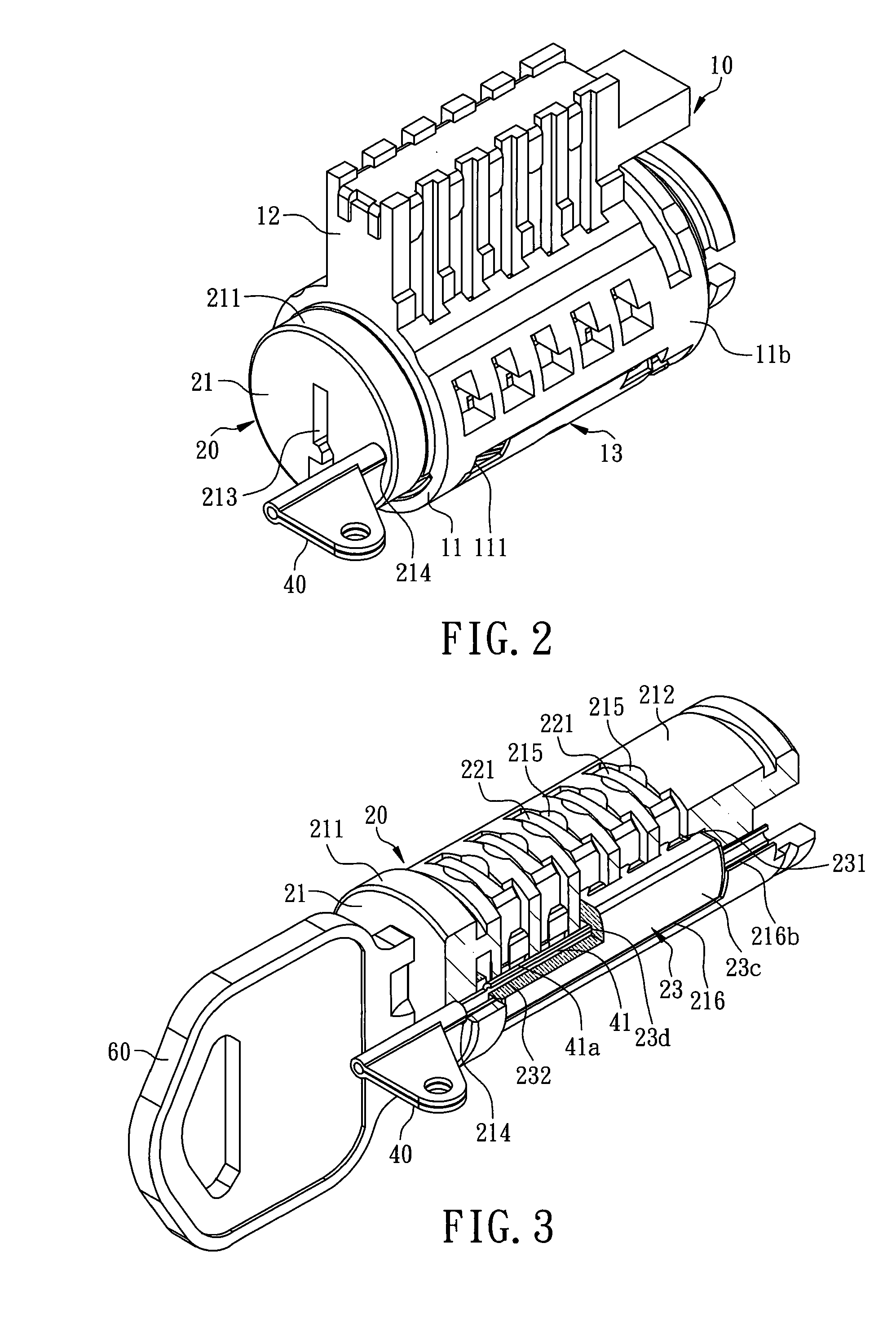
[0031]With reference to FIGS. 1 and 2, a rekeyable lock cylinder according to the first preferred embodiment of the present invention comprises a cylinder body 10, a plug assembly 20 disposed within the cylinder body 10 and a plurality of upper pins 30. The cylinder body 10 comprises a hollow cylinder portion 11 used for disposing the plug assembly 20, an extending protrusion 12 formed at one side of the hollow cylinder portion 11 and a biasing element 13 disposed at the hollow cylinder portion 11, however, the extending protrusion 12 can be omitted from the cylinder body 10 in another embodiment. In this embodiment, the hollow cylinder portion 11 has an inside wall 11a, an outside wall 11b and a recession 111 recessed from the inside wall 11a, wherein the recession 111 communicates with the inside wall 11a and the outside wall 11b. The extending protrusion 12 has a plurality of upper pin holes 121 in communication with the hollow cylinder portion 11. With reference to FIGS. 1, 2 an...


PUM


Abstract

A rekeyable lock cylinder comprises a cylinder body and a plug assembly disposed within the cylinder body. The plug assembly comprises a plug body, a plurality of assembled pins and a position block. The plug body has a longitudinal axis, a transverse axis vertical to the longitudinal axis, a keyhole and a first through hole. Each of the assembled pins is movably disposed in the plug body and comprises a first rack component and a second rack component selectively engaging with the first rack component. The position block disposed at the plug body has a plurality of pin runners used for disposing the first rack components, a second through hole corresponding to the first through hole and a tool-contacting surface located within the second through hole. The position block can move along the transverse axis-direction of the plug body to make each of the first rack components reengage with each of the second rack components.

Description

[0001]This application is a Continuation-in-Part of application Ser. No. 12 / 149,757, filed on 7 May 2008, now U.S. Pat. No. 7,624,606 and for which priority is claimed under 35 U.S.C. §120; the entire contents of which are hereby incorporated by reference.FIELD OF THE INVENTION[0002]The present invention relates to a lock cylinder, more particularly to a rekeyable lock cylinder and operating method thereof with reinforced burglarproof.BACKGROUND OF THE INVENTION[0003]It is almost required to release mutual engagement of racks at first during rekeying process of known rekeyable lock cylinder and reengage racks after rekeying, such as U.S. Pat. No. 6,860,131 “rekeying a lock assembly” discloses a simple tool used for pushing linkage mechanism within a lock to rekey. However, linkage mechanism of the foregoing lock cylinder lacks burglarproof in design when rekeying as well as the simple tool is easy to obtain, that might be subject to unauthorized rekeying operation resulting in secur...

Claims


Application Information

Patent Timeline
Patent Type & Authority Patents(United States)
IPC IPC(8): E05B27/04E05B29/06
CPCE05B29/004Y10T70/7734Y10T70/7559Y10T70/7746Y10T70/7605Y10T70/7452Y10T70/778Y10T70/7644Y10T70/7616Y10T70/7463Y10T70/774Y10T70/7599
Inventor HUANG, CHAO-MINGCHEN, CHI-MING
Owner TAIWAN FU HSING INDAL
Why Eureka
Try Eureka