
Spray nozzle comprising axial grooves to provide a balance supply to the vortex chamber

a technology of axial grooves and spray nozzles, which is applied in the direction of liquid/fluent solid measurement, combustion process, volume measurement, etc., can solve the problems of inability to ensure the aerosol features and the orientation cannot be imposed on the assembly lin

Active Publication Date: 2011-05-10
ALBEA LE TREPORT
View PDF7 Cites 19 Cited by
  • Summary
  • Abstract
  • Description
  • Claims
  • Application Information

AI Technical Summary

Benefits of technology

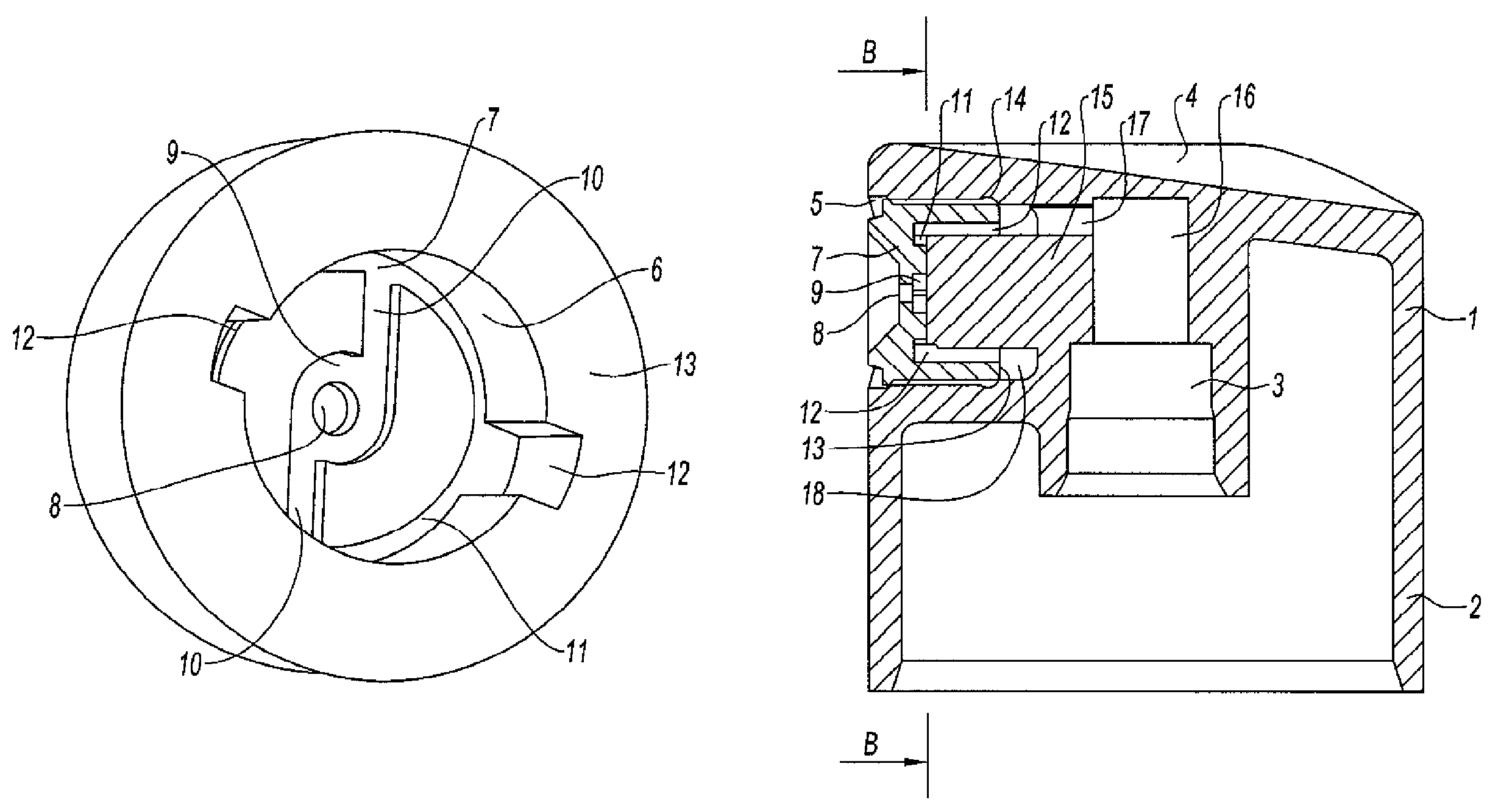
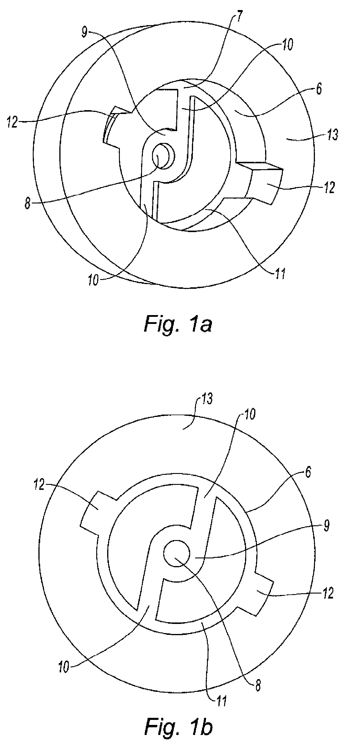
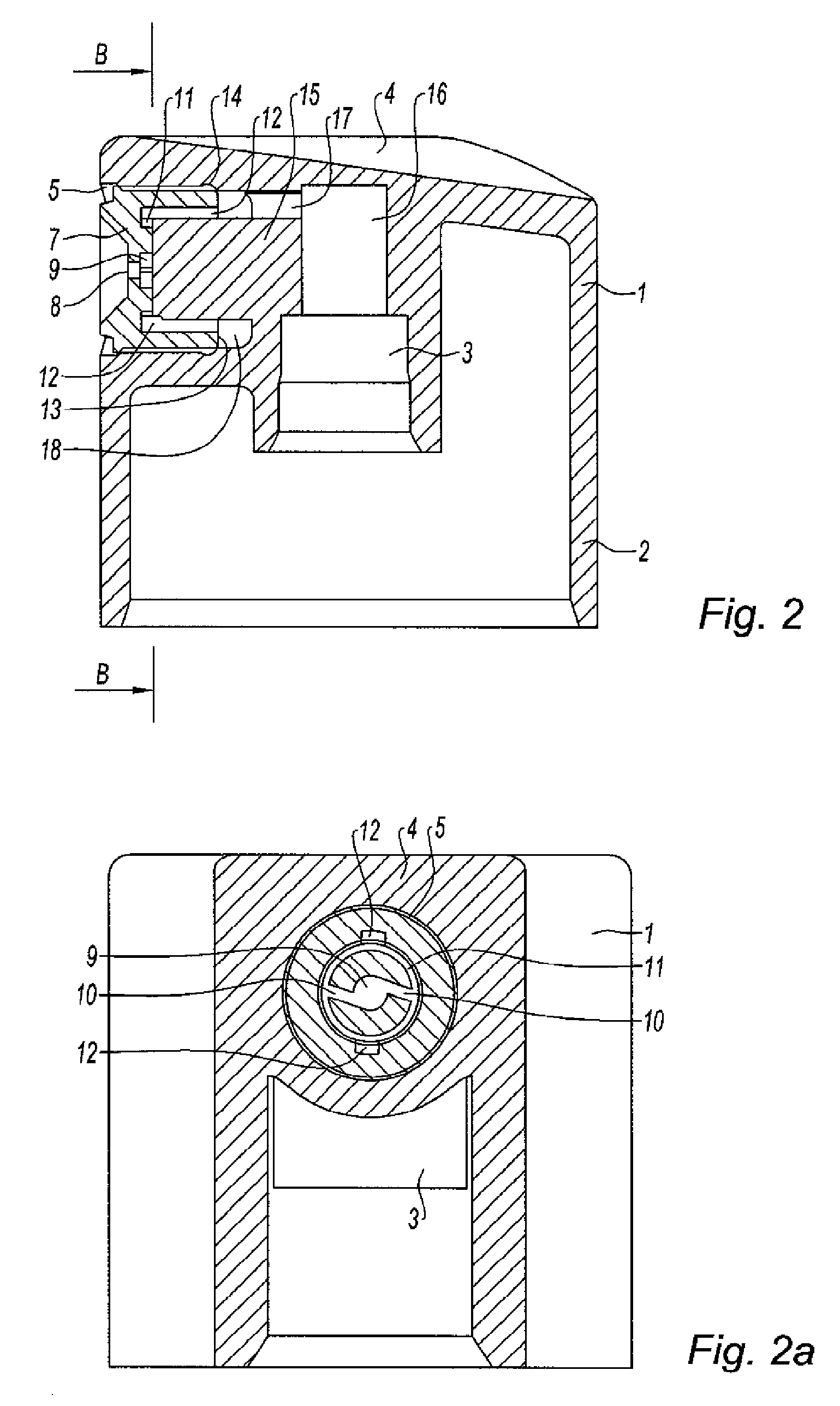
"The invention proposes a spray nozzle that can produce an aerosol without being affected by the position of the nozzle in the push button. The nozzle has a body with an assembly tube, a vortex chamber, and two radial tubes to supply liquid to the vortex chamber. The lateral inside wall of the tube has two axial grooves that are positioned angularly so that each downstream end of a groove is equidistant from the two upstream ends of the tube that are adjacent to it on either side along the length of the annular duct. This design ensures consistent and efficient spraying of liquid. The invention also includes a push button with a distribution path and a spray nozzle associated inside the push button. The liquid distribution system also includes a pump or manually actuated valve for spraying liquid."

Problems solved by technology

However, this orientation cannot be imposed on the assembly lines, resulting in aerosols that are randomly different with distribution systems comprising a same nozzle-push button assembly.
Consequently, the features of the aerosol may not be guaranteed, which is detrimental for technical reasons for the use of the aerosol as well as for human health reasons as droplets that are too fine may be inhaled by the user.

Method used


Image

  • Spray nozzle comprising axial grooves to provide a balance supply to the vortex chamber
  • Spray nozzle comprising axial grooves to provide a balance supply to the vortex chamber
  • Spray nozzle comprising axial grooves to provide a balance supply to the vortex chamber

Examples


Embodiment Construction

[0017]In relation to the FIG. 2, a spray push button for a liquid distribution system is described below, wherein said liquid may be of any nature, especially used for perfumery, cosmetics or pharmaceutical treatments.

[0018]The push button comprises a body 1 inside which a distribution path is formed. Furthermore, the body 1 has an annular skirt with an aspect 2 that is surmounted by a cavity 3 for assembling the push button onto the distribution system. Moreover, the push button comprises an upper zone 4 allowing the user to exert finger pressure on said push button in order to move it axially.

[0019]In particular, the distribution system may comprise a jet (not shown) that is inserted imperviously into the cavity 3. As may be found in the prior art, the distribution system further comprises means for assembling it onto a bottle containing the liquid and means for removing the liquid from inside said bottle that are fitted so as to supply the jet with a pressurised liquid.

[0020]For ...


PUM


Abstract

A spray nozzle designed to be mounted in a push button of a liquid distribution system, including a body equipped with an assembly tube that is defined by a front wall in which a distribution orifice is formed, wherein the inside face of the front wall is equipped with a vortex chamber that communicates with the distribution orifice, at least two radial tubes to supply liquid to the vortex chamber, and an annular duct to supply liquid to the upstream end of the tubes, in which the lateral inside wall of the tube is equipped with at least two axial grooves which respectively extend between an upstream end opening onto the rear edge of the tube and a downstream end opening onto the annular duct, wherein the grooves are positioned angularly so that each downstream end of a groove is equidistant from the two upstream ends of the tube adjacent to it on either side along the length of the annular duct.

Description

CROSS REFERENCED APPLICATIONS[0001]The present application claims priority of French patent application No. 07 04373 filed on Jun. 19, 2007, the content of which is incorporated herein by reference.FIELD OF THE INVENTION[0002]The invention relates to a spray nozzle designed to be mounted in a push button of a liquid distribution system, such a push button and such a distribution system.BACKGROUND OF THE INVENTION[0003]In one specific application, the distribution system is designed to equip bottles used for perfumery, cosmetics or pharmaceutical treatments. Indeed, this type of bottle contains a liquid that is distributed by a distribution system comprising a pump or a manually actuated valve, wherein said system is actuated by a push button to allow the liquid to be sprayed.[0004]Such push buttons are normally made of two parts: an actuator body and a spray nozzle for the liquid which are associated to one another to form the push button. In particular, the spray nozzle may also be...

Claims


Application Information

Patent Timeline
Patent Type & Authority Patents(United States)
IPC IPC(8): B05B1/34B67D7/60
CPCB05B1/3436
Inventor OCTEAU, JEAN-LUCDUMONT, PIERRESONGBE, JEAN-PIERREIMENEZ, HERVE
Owner ALBEA LE TREPORT
Learn More