Wiring holding unit

a technology of holding unit and wiring, which is applied in the direction of machine supports, transportation and packaging, and other domestic objects, can solve the problems of difficulty in meeting demand of this structure, and achieve the effect of positive maintenance of sufficient retaining for

Inactive Publication Date: 2011-05-10
ELECTRONICS & TELECOMM RES INST +1
View PDF34 Cites 33 Cited by
  • Summary
  • Abstract
  • Description
  • Claims
  • Application Information

AI Technical Summary

Benefits of technology

[0018]In the wiring holding unit of the invention, when the pair of gripping portions are moved through the movable portion to grip the receiving member, the gripping member grips the receiving member. The fitting / fixing member is moved toward the gripping member in the direction generally perpendicular to the direction of fixing of the receiving member, and is fitted on the gripping member to be fixed thereto, thereby preventing the pair of gripping portions, gripping the receiving member, from moving respectively in the reverse directions.
[0023](4) In the wiring holding unit of the invention, a limitation device may be provided at least one of the gripping member and the fitting / fixing member, and when the gripping member and the fitting / fixing member are fitted together, the limitation device prevents the fitting / fixing member from moving in a direction away from the gripping member.
[0024]In the wiring holding unit of the invention, when the gripping member and the fitting / fixing member are fitted together, the fitting / fixing member is prevented by the limitation device from being moved in the direction away from the gripping member.
[0025]As described above, in the wiring holding unit of the invention, the pair of gripping portions are moved through the movable portion to grip the receiving member, and thus the receiving member is gripped by the gripping member, and then the fitting / fixing member is moved toward the gripping member in the direction perpendicular to the direction of fixing of the receiving member, and is fitted on the gripping member to be fixed thereto, thereby preventing the pair of gripping portions, gripping the receiving member, from moving respectively in the reverse directions. Therefore, the direction of fitting of the gripping member and the fitting / fixing member relative to each other can be made the same as the direction of mounting of the receiving member on the gripping member, and therefore the receiving member, the gripping member and the fitting / fixing member can be automatically assembled together by a machine. And besides, the gripping member is fittingly fixed by the fitting / fixing member, and therefore a sufficient retaining force can be obtained regardless of the diameter, cross-sectional shape, etc., of the receiving member. Therefore, there can be provided the wiring holding unit which can meet the demand for the automatic production by the machine.
[0026]In the invention, the pair of gripping portions are caused to grip the receiving member when the movable portion of the gripping member is pressed by the receiving member. Therefore, merely by bringing the receiving member into abutting engagement with the movable portion and then by pressing the receiving member, the receiving member can be easily gripped by the gripping member. Therefore, this wire holding unit can more easily meet the demand for the automatic production by the machine.
[0028]In the invention, when the gripping member and the fitting / fixing member are fitted together, the fitting / fixing member is prevented by the limitation device from being moved in the direction away from the gripping member. Therefore, the fitting / fixing member is prevented from being disengaged from the gripping member, and therefore the sufficient retaining force can be positively maintained. And besides, it is only necessary to fit the fitting / fixing member on the gripping member, and therefore the wiring holding unit can more easily meet the demand for the automatic production by the machine.

Problems solved by technology

Therefore, it has been difficult to effect the mounting operation from one direction because of the necessity of the pivotally-moving operation for the pivotal portion 130, etc., and therefore it has been difficult for this structure to meet a demand for an automatic production by a machine.

Method used


Image

  • Wiring holding unit
  • Wiring holding unit
  • Wiring holding unit

Examples


Embodiment Construction

[0036]One preferred embodiment of a wiring holding unit of the present invention will now be described with reference to FIGS. 1 to 6.

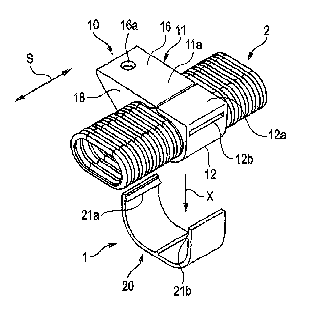
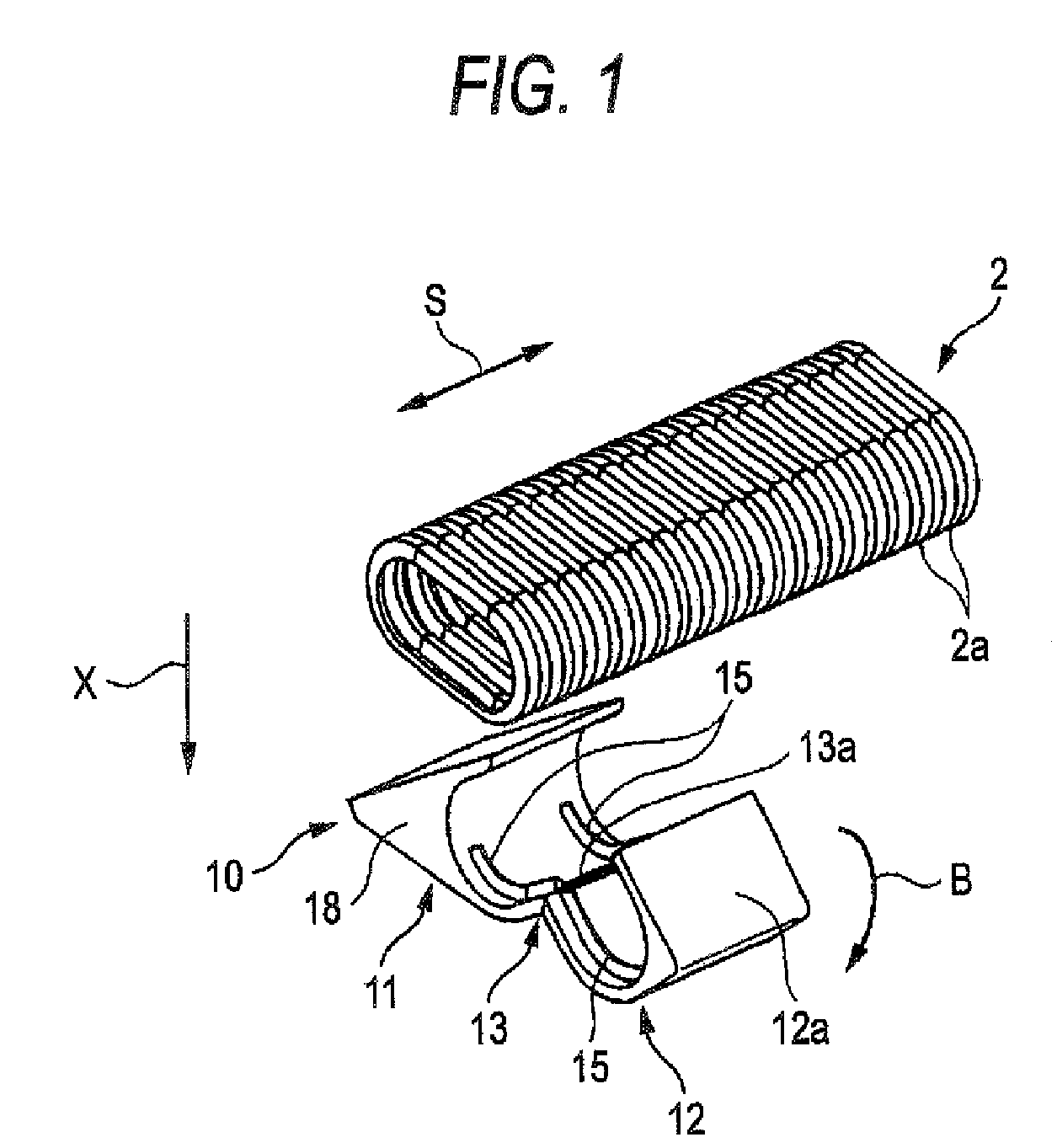
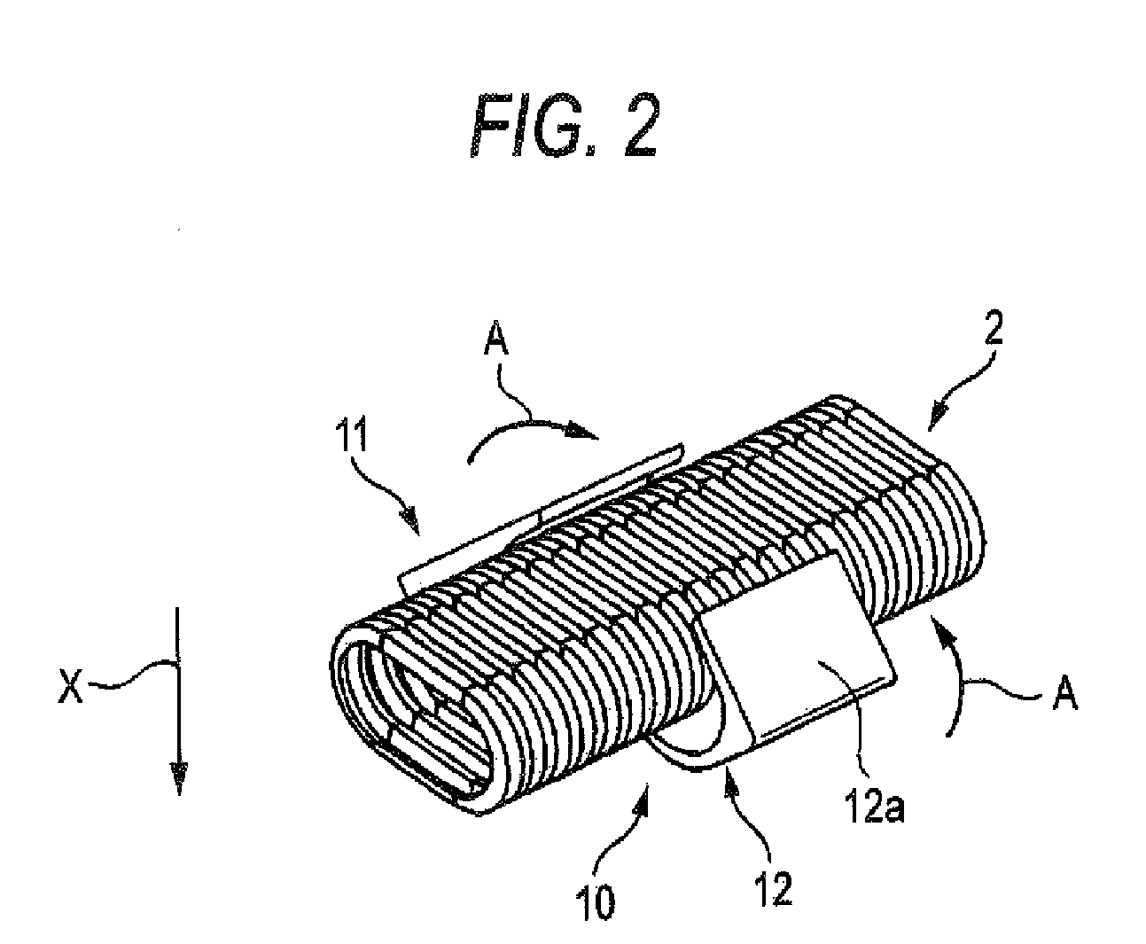
[0037]In FIGS. 1 to 6, the wiring holding unit 1 holds a corrugated tube (receiving member) 2 of a generally oval tubular shape (in which wire harnesses (not shown) serving as wiring are received). This wiring holding unit 1 comprises a gripping member 10 for gripping the corrugated tube 2, and a fitting / fixing member 20 for fitting on the gripping member 10 to fix the same.

[0038]As described above, the wire harness comprises a plurality of wires, and connectors secured to end portions of the wires. However, any other suitable type such as one or a plurality of wires or a cable can be used as the wiring.

[0039]The corrugated tube 2 is made of a synthetic resin or the like, and is formed into a generally oval tubular shape. The plurality of wire harnesses (serving as the wiring) are passed through and received in the interior of the corrugated tube 2. A...


PUM


Abstract

A wiring holding unit for holding a tubular receiving member receiving wiring therein includes a gripping member including a pair of gripping portions for gripping the receiving member, and a movable portion interconnecting the pair of gripping portions such that the pair of gripping portions are movable, and a fitting / fixing member which is separate from the gripping member, and is moved toward the gripping member in a direction generally perpendicular to a direction of fixing of the receiving member gripped by the gripping member, and is fitted on the gripping member to be fixed thereto, thereby preventing the pair of gripping portions from moving respectively in directions opposite respectively to gripping directions of the pair of gripping portions.

Description

BACKGROUND OF THE INVENTION[0001]1. Field of the Invention[0002]This invention relates to a wiring holding unit for holding wiring.[0003]2. Related Art[0004]Various electronic equipments are mounted on an automobile serving as a mobile body. Therefore, wire harnesses are installed in the automobile so as to supply electric power from a power source or the like to the electronic equipments and also to transmit control signals from a computer or the like to the electronic equipments. The wire harness comprises a plurality of wires, and connectors secured to end portions of the wires.[0005]The wire comprises an electrically-conductive conductor, and a sheath portion which is made of an insulative synthetic resin and covers the conductor. The wire is a so-called sheathed wire. The connector comprises electrically-conductive metal terminals, and an insulative connector housing. The metal terminal is secured to the end portion or other portion of the wire, and is electrically connected to...

Claims


Application Information

Patent Timeline
Patent Type & Authority Patents(United States)
IPC IPC(8): F16L3/08
CPCF16L3/1025H02G3/0468B60R16/0215H02G3/32H02G3/0691
Inventor OGA, TATSUYATSUKAMOTO, AKIHITOTAKAMATSU, MASAHIRONOMURA, KOJI
Owner ELECTRONICS & TELECOMM RES INST
Why Eureka
Try Eureka