Eureka AIR delivers breakthrough ideas for toughest innovation challenges, trusted by R&D personnel around the world.

Interlocking trigger assembly for a suturing device

a trigger assembly and suturing device technology, applied in the field of suturing devices, can solve the problems of limiting the ability to manipulate the needle and suture, no control of the timing of the needle deployment, and the inability to control the distance between the upper and lower jaws, etc., to achieve the effect of soft tissue damag

Inactive Publication Date: 2011-05-10
SPECIALTY SURGICAL INSTR INC +1
View PDF9 Cites 18 Cited by
  • Summary
  • Abstract
  • Description
  • Claims
  • Application Information

AI Technical Summary

Benefits of technology

[0006]The present invention solves the problem of premature needle deployment in a suturing device by employing an interlocking trigger mechanism. The interlocking trigger mechanism accomplishes this by making the needle deployment trigger action dependent on the position of the jaw actuation handle. When the jaw actuation handle is in its forward position, and therefore the upper jaw is open beyond the maximum deployment position, the needle deployment trigger is blocked from moving by a portion of the jaw actuation handle. The jaw actuation handle is constructed such that once it reaches the proper position, it ceases to block the needle deployment trigger, and allows it to move, effectively interlocking the needle deployment trigger to the jaw actuation handle.
[0011]Among the advantages of this invention may be one or more of the following. The interlocking mechanism ensures that the needle / suture is deployed only when the upper jaw is below a maximum allowable distance from the lower jaw. This prevents premature needle deployment and thereby soft tissue damage from multiple unsuccessful attempts.

Problems solved by technology

However, in endoscopic or other minimally invasive surgical procedures that require suturing of internal tissues access to the suturing area is limited and this limits the ability to manipulate the needle and suture.
In this prior art suturing devices there is no control of the distance between the upper and lower jaw and of the timing when the needle is deployed.
As a result, in some cases, the needle is deployed prematurely, i.e., the needle is engaged in tissue, but not captured by the upper jaw.
When premature needle deployment occurs, the suturing action needs to be repeated.
Multiple premature needle deployments may results in soft tissue damage.
Another problem of premature deployment is that it is difficult to back the needle out once it is into tissue but cannot be captured on the other side.

Method used


Image

  • Interlocking trigger assembly for a suturing device
  • Interlocking trigger assembly for a suturing device
  • Interlocking trigger assembly for a suturing device

Examples


Embodiment Construction

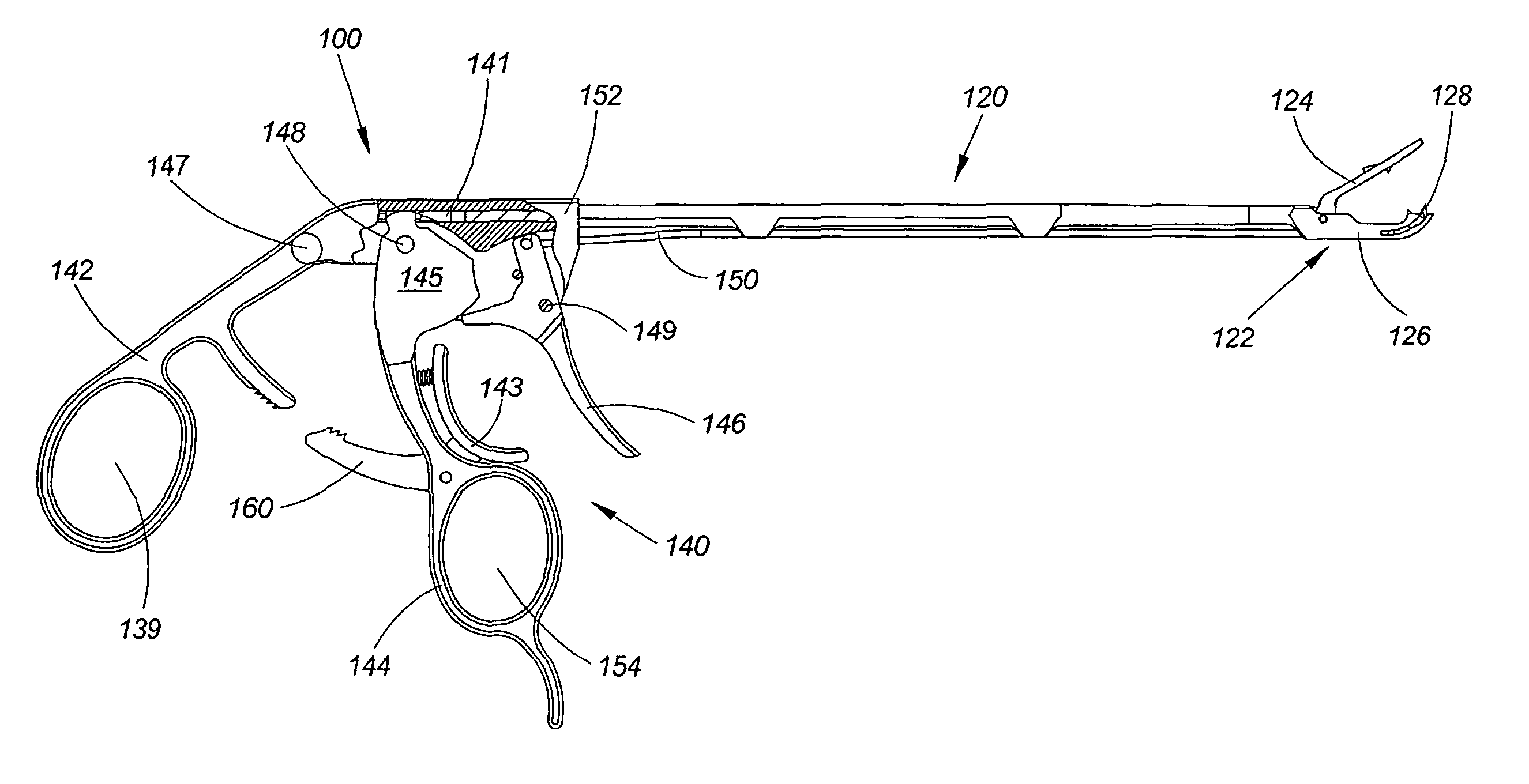
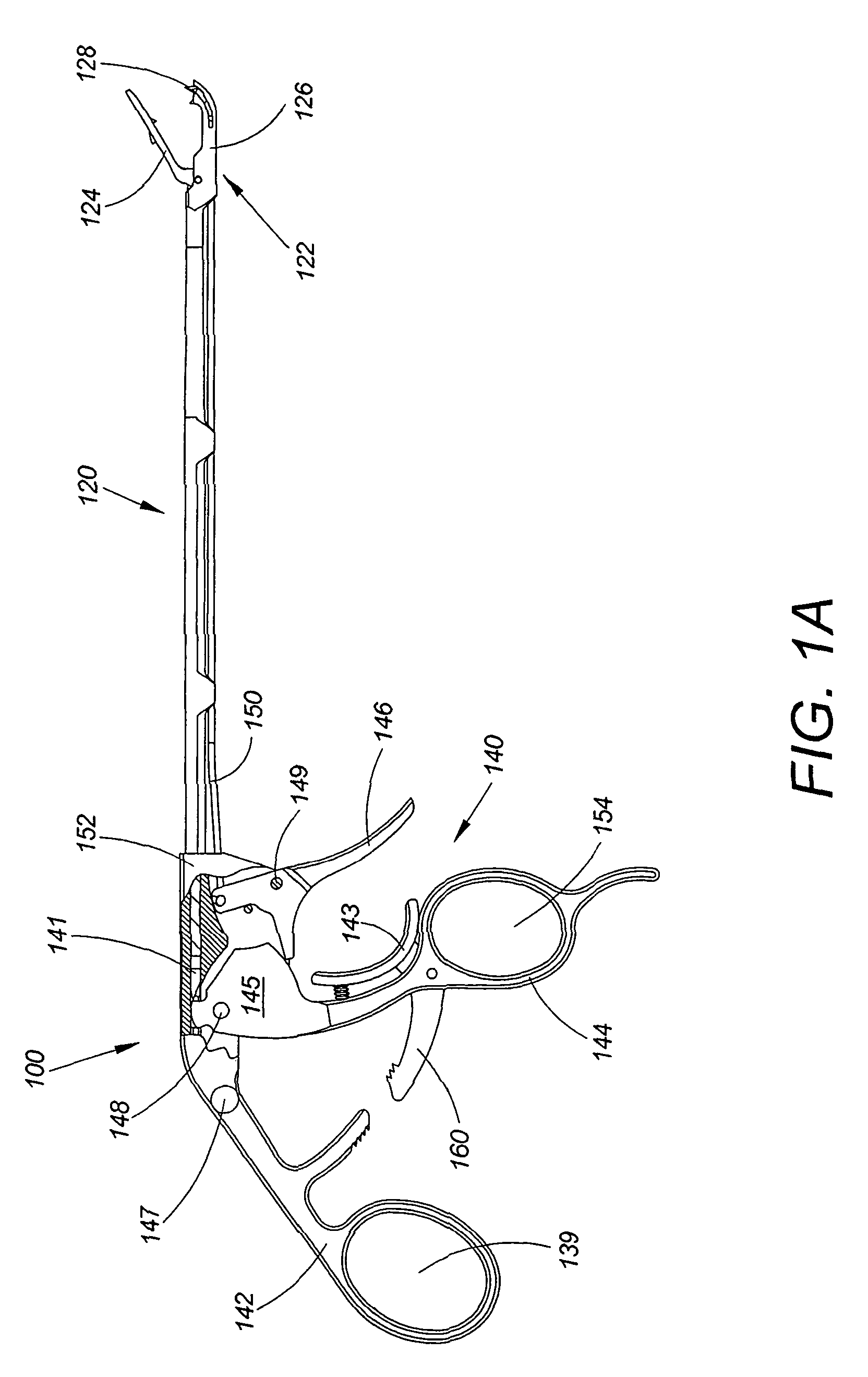
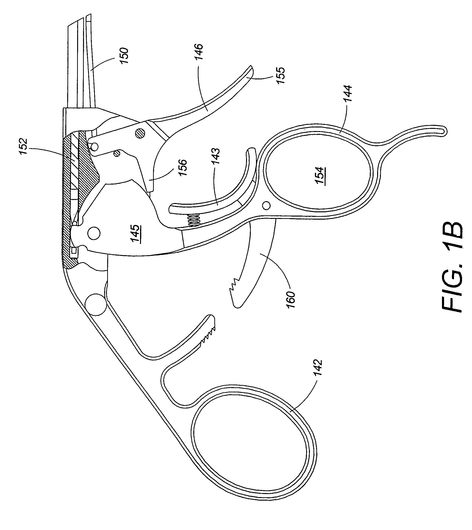
[0024]Referring to FIG. 1A, the endoscopic instrument 100 includes a front end assembly 120 with an end effector 122, and a handle assembly 140. The end effector 122 includes a movable upper jaw 124, a lower jaw, 126 and a needle / suture mechanism 128. The handle assembly 140 includes a stationary handle 142, a movable handle 144, a trigger 146 and a base 141, also shown in FIG. 1B and FIG. 1C. Stationary handle 142 is attached to the base 141 and movable handle 144 and trigger 146 are pivotally attached to the base 141 via pivot mechanisms 148 and 149, respectively. In the embodiment of FIG. 1B movable handle 144 is secured at a predetermined distance relative to the stationary handle 142 via a ratchet mechanism 160. Movable handle 144 is further connected to the movable upper jaw 124 via an actuator rod 152. Actuator rod 152 translates the motion of the movable handle 144 into a motion of the upper jaw 124. Trigger 146 is further connected to the needle / suture mechanism 128 via a s...


PUM


Abstract

An endoscopic suturing device having an interlocking trigger assembly for preventing premature needle deployment. The suturing device comprises a handle assembly that includes a movable handle interlocking with a trigger. The suturing device further comprises an end effector having an upper jaw, a lower jaw and a needle / suture mechanism. The motion of the movable handle causes the upper jaw to move relative to the lower jaw. The activation of the trigger causes deployment of the needle / suture mechanism. The interlocking mechanism ensures that the needle / suture is deployed only when the upper jaw is below a maximum allowable distance from the lower jaw.

Description

CROSS REFERENCE TO RELATED CO-PENDING APPLICATIONS[0001]This application claims the benefit of U.S. provisional application Ser. No. 60 / 478,670 filed on Jun. 13, 2003 and entitled INTERLOCKING TRIGGER ASSEMBLY FOR A SUTURING DEVICE which is commonly assigned and the contents of which are expressly incorporated herein by reference.FIELD OF THE INVENTION[0002]The present invention relates to a suturing device, and more particularly to a suturing device with an interlocking trigger assembly.BACKGROUND OF THE INVENTION[0003]Suturing or stitching of tissue is performed in surgical procedures or other cases where closing of incisions or cuts is required. Suturing is usually performed by grasping the tissue to be sutured, pushing a first end of a needle having a needle tip through one side of the tissue and then grasping the needle tip from the other side of the tissue to pull the needle through. The needle and a suture attached to a second end of the needle are then pulled through the tis...

Claims


Application Information

Patent Timeline
IPC IPC(8): A61B17/04A61B17/12A61B17/00A61B17/28A61B19/00
CPCA61B17/0469A61B17/29A61B2019/4857A61B2017/047A61B2017/2912A61B2017/00115A61B17/0625A61B2090/0811
Inventor DIFRANCESCO, FRANCIS J.GRIFFITHS, JERRY R.
Owner SPECIALTY SURGICAL INSTR INC
Why Eureka
Eureka Blog
Learn More