Eureka AIR delivers breakthrough ideas for toughest innovation challenges, trusted by R&D personnel around the world.

Apparatus for accessing and storing objects

a technology for objects and apparatus, applied in the direction of transportation items, energy efficiency in elevators, locomotives, etc., can solve the problems of injury to users, damage to vehicles, and difficulty in moving large objects such as ladders or heavy objects such as tool boxes between these lower and higher positions, and achieve the effect of interlocking

Active Publication Date: 2015-04-21
DIVERDI MARC A
View PDF50 Cites 2 Cited by
  • Summary
  • Abstract
  • Description
  • Claims
  • Application Information

AI Technical Summary

Benefits of technology

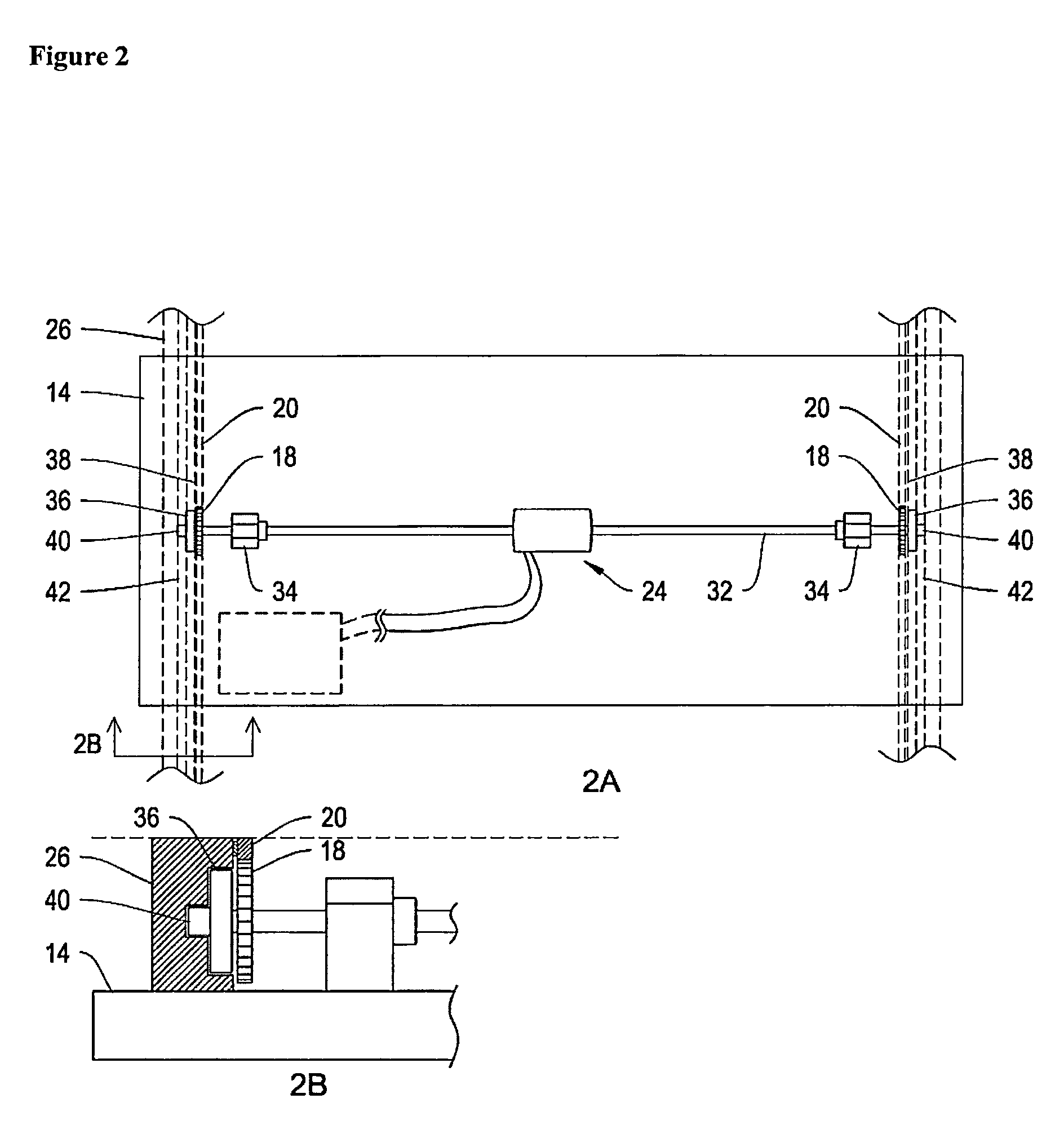
[0029]In another aspect, the present invention relates to an apparatus for transferring an object between an upper storage position and a lower accessible position comprising: a stationary mounting frame comprising two tracks each having a rail capable of effectively interlocking with at least one gear; and at least one carriage positioned between the tracks comprising: a) a tray having two distal ends, b) a gear at each distal end effectively interlocking with two additional gears that interlock with the rail, c) an object fastener attached to the tray, and d) a power drive operatively attached to the tray capable of rotating one or both of the gears at each distal end. In a further embodiment, the mounting frame is attached to a vehicle. In a further embodiment, the mounting frame traverses the top and one side of the vehicle. In a further embodiment, the mounting frame traverses the top and two sides of the vehicle. In a further embodiment, the rail is an array of teeth capable of effectively interlocking with the two additional gears.
[0039]In another aspect, the present invention relates to a method of loading an object onto a vehicle comprising: 1) fastening the object to a carriage in a lower accessible position wherein the carriage comprises: a) a tray having two distal ends, b) a gear at each distal end effectively interacting with an additional two gears that effectively interact with a rail within a track mounted to the vehicle, c) an object fastener capable of securing the object to the tray, and d) a power drive operatively attached to the tray and capable of rotating one or both of the gears; 2) initiating the power drive and rotating the gears in a direction that moves the carriage in an upward direction; and 3) stopping the power drive when the carriage has reached an upper storage position. In a further embodiment, the rail is an array of teeth capable of effectively interlocking with the two gears.

Problems solved by technology

For the craftsman or sports enthusiast, movement of these objects on and off the vehicle is difficult and in cases of heavier objects can be dangerous, especially under in climate weather conditions such as snow and ice.
Movement of larger, elongated objects such as ladders or heavy objects such as tool boxes between these lower and higher positions still requires a significant amount of effort on the part of the user.
Lowering an elongated or heavy object, or both, can be especially dangerous if done too rapidly, potentially causing injury to the user or damage to the vehicle.
U.S. Pat. No. 7,384,093 discloses a vehicle comprising an apparatus for moving an object between a use position and a stowed position, but the apparatus is constructed within the vehicle and is not practical for large objects such as a ladder.
The apparatus, however, is limited in the variety of material it can carry by the space along side of the panel truck, and lacks the ability to move an object from a lower accessible position to an upper storage position.
Although convenient for bicycles, such a winch and cable system is not ideal for heavier objects such as equipment and tools used by the average craftsman.
The apparatus, however, lacks general utility for objects other than a ladder.
The power drive also requires many moving parts and cables making it impractical for vehicles other than emergency vehicles.
As the two cylinders wear down from general use such coordination will become more difficult.
The complexity of the system also makes it impractical for non-emergency vehicles.
However, the cargo frame requires a network of supports pivotally attached to each other to move the cargo between the two positions which may be difficult to operate, even with the hydraulic assist, under in climate weather conditions.
Although the utility rack can be used on non-emergency vehicles, the wide range of motion necessary for the operator to achieve is difficult with heavier objects or with multiple ladders.

Method used


Image

  • Apparatus for accessing and storing objects
  • Apparatus for accessing and storing objects
  • Apparatus for accessing and storing objects

Examples


Embodiment Construction

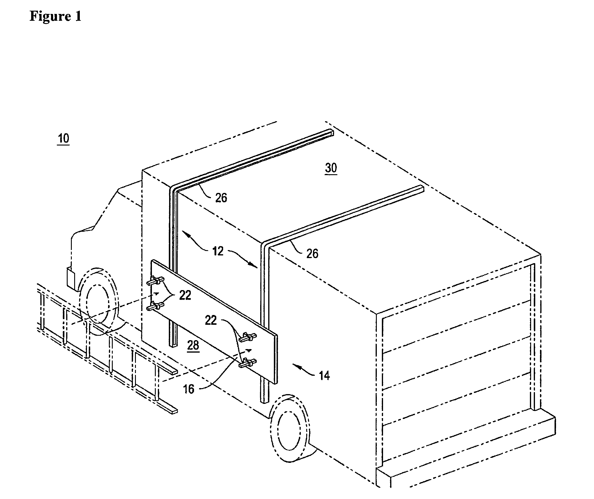
[0064]The apparatus of the present invention for storing and accessing objects can be used in any application or environment, but has a particular advantage when used on a vehicle. Accordingly, although the apparatus in the accompanying figures and described hereinafter is for a vehicular application, it should be noted that this application is presented by way of example only, and does not indicate or imply that the present invention is limited to vehicular applications. Similarly, the apparatus of the present invention is illustrated and described for use on a truck, but can instead be used on any other type of vehicle desired.

[0065]The apparatus for storing and accessing an object of the present invention (indicated generally as 10 in the figures) has mounting frame 12, and one or more carriages 14, comprising a tray 16 having two distal ends, a gear 18 at each distal end effectively interlocking with a rail 20, an object fastener 22 attached to tray 16, and a power drive 24 oper...


PUM


Abstract

The present invention relates to an apparatus for transferring an object from a lower accessible position to a higher storage position, which is particularly useful on vehicles. The present invention also relates to a method of transferring an object from a lower accessible position to a higher storage position.

Description

CROSS REFERENCE TO RELATED APPLICATIONS[0001]This application is a continuation-in-part of and claims the benefit of priority under 35 U.S.C. §120 to U.S. patent application Ser. No. 12 / 583,195, filed Aug. 14, 2009, which is a continuation-in-part of and claims the benefit of priority under 35 U.S.C. §120 to U.S. patent application Ser. No. 12 / 383,106, filed Mar. 19, 2009, now abandoned, which claims the benefit of priority under 35 U.S.C. §119 to U.S. provisional patent application Ser. No. 61 / 070,090, filed Mar. 20, 2008, the entire contents of all applications are incorporated herein by reference.BACKGROUND OF THE INVENTION[0002]Numerous utility apparatuses exist for storing objects on a vehicle. Vehicle racks for vans and pick up trucks, for example, have been designed to transport a wide variety of objects including tools and implements such as ladders, pipes, tool boxes, building materials, rakes, shovels, brooms and sporting equipment such as skis, surfboards, bicycles, kayak...

Claims


Application Information

Patent Timeline
Patent Type & Authority Patents(United States)
IPC IPC(8): B60P3/10B60P3/40B60R9/042E06C5/02
CPCB60R9/042B60R9/0423B60P3/40E06C5/02Y02B50/144Y02B50/00
Inventor DIVERDI, MARC ANTHONY
Owner DIVERDI MARC A
Why Eureka
Eureka Blog
Learn More