
Lens barrel and imaging device

Inactive Publication Date: 2008-08-28
CANON KK
View PDF6 Cites 2 Cited by
  • Summary
  • Abstract
  • Description
  • Claims
  • Application Information

AI Technical Summary

Benefits of technology

[0025]The present invention enables efficient interlock between a cylindrical member such as a moving cam ring and a component such as a viewfinder cam plate or a strobe cam plate, without size-increasing.

Problems solved by technology

The resulting construction constraints cause a problem in that the thickness of the barrel has to increase in the optical axis direction.

Method used


Image

  • Lens barrel and imaging device
  • Lens barrel and imaging device
  • Lens barrel and imaging device

Examples


Embodiment Construction

[0035]The present invention will now be described in detail with reference to the drawings showing preferred embodiments thereof.

[0036]

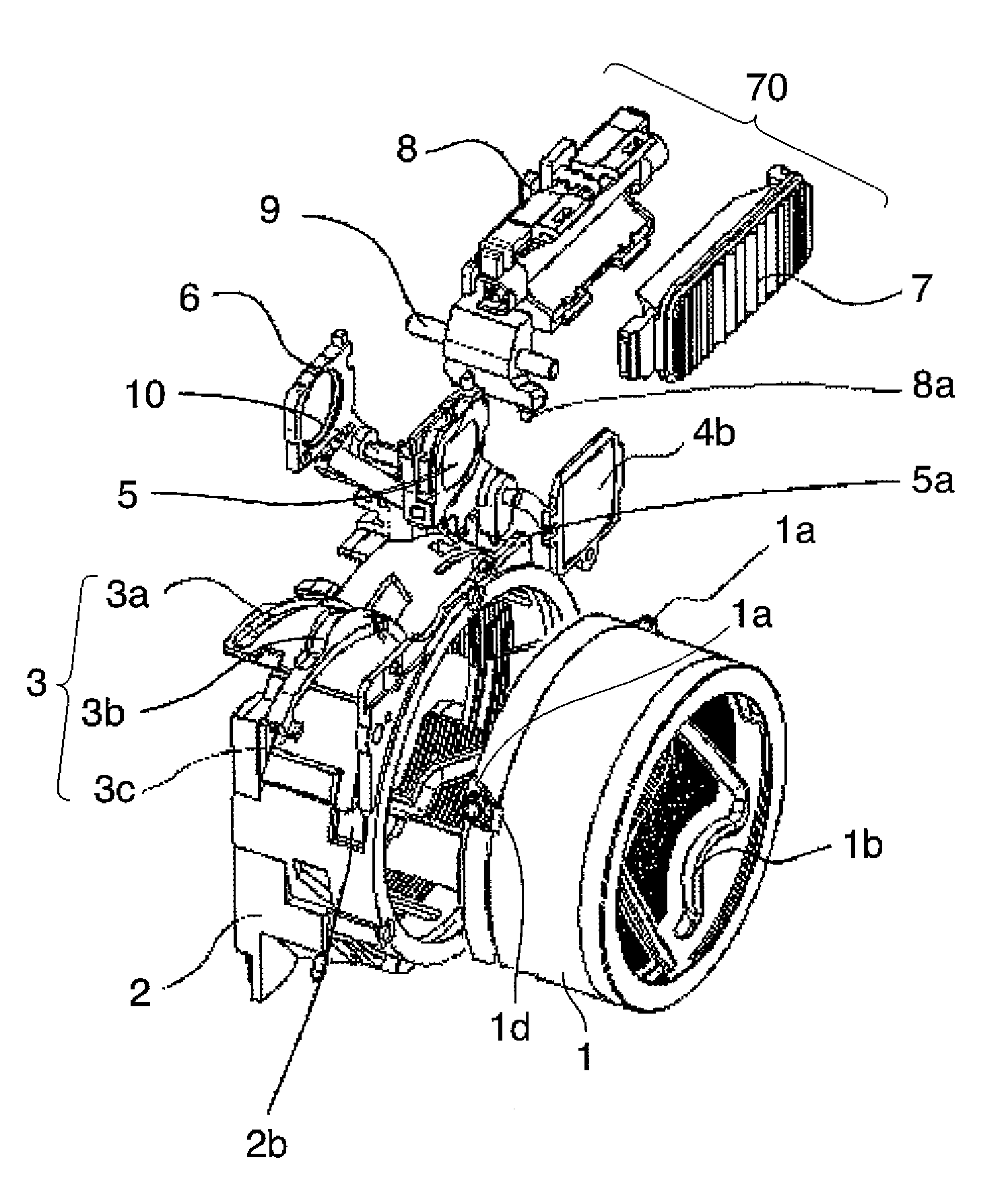
[0037]A construction of an imaging device, such as a digital camera, including a barrel lens according to an embodiment of the present invention is described below with reference to FIGS. 1A and 1B, and FIGS. 2A to 2C.

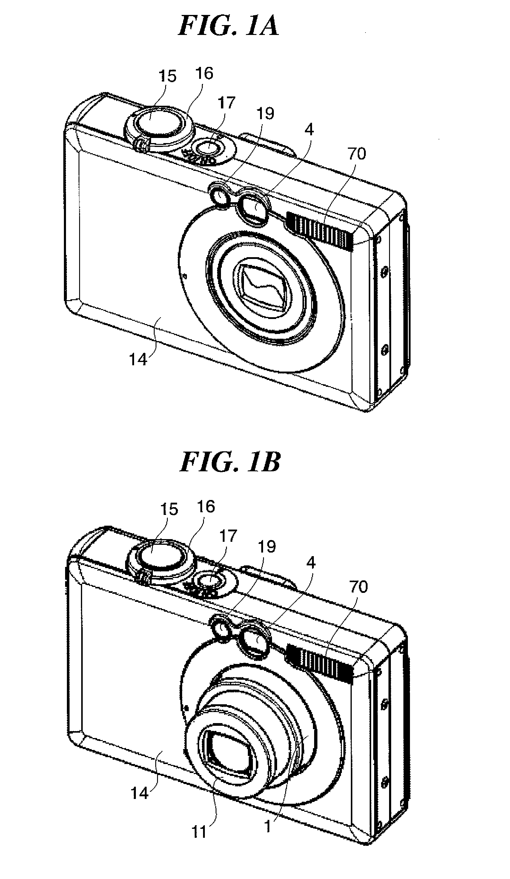
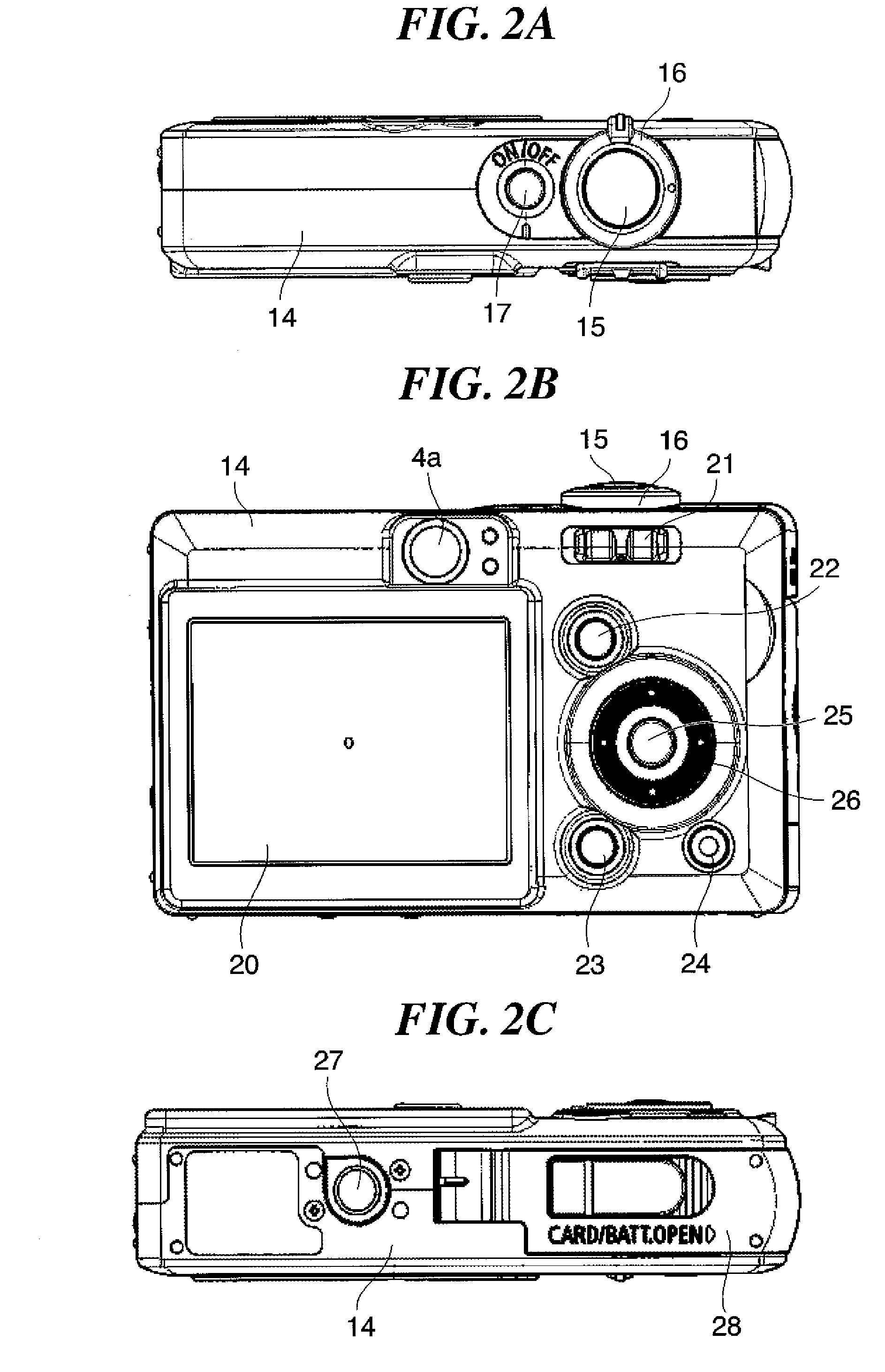
[0038]FIGS. 1A and 1B are external perspective views of a digital camera that is an imaging device including a barrel lens according to an embodiment of the present invention. FIG. 1A shows a state in which the power is switched off in the digital camera, and FIG. 1B shows a state in which the power is switched on. FIGS. 2A to 2C are external views of the digital camera of FIG. 1. FIG. 2A is a top view, FIG. 2B is a rear view, and FIG. 2C is a bottom view.

[0039]As shown in FIGS. 1A and 1B, a digital camera 14 includes a zoom mechanism to enable a degree of magnification to be altered during imaging. The digital camera 14 includes, on a ...


PUM


Abstract

A lens barrel which allows efficient interlock between a cylindrical member such as a moving cam ring and a component such as a viewfinder cam plate or a strobe cam plate, without size-increasing. The lens barrel comprises a first cylindrical member, and a second cylindrical member that is disposed so as to receive the first cylindrical member, and includes a guiding part at an inner circumferential surface thereof. The guiding part includes a groove-form hole part that penetrates the second cylindrical member, and the first cylindrical member includes a follower part that follows the guiding part having the groove-form hole part.

Description

BACKGROUND OF THE INVENTION[0001]1. Field of the Invention[0002]The present invention relates to a lens barrel having an imaging lens, and an imaging device such as a camera or the like with the lens barrel provided therein.[0003]2. Description of the Related Art[0004]Many of the digital cameras which have been widely adopted in recent years include a viewfinder to allow a user to determine an angle of view of a subject. Many of these digital cameras also include a strobe mechanism to illuminate of the subject with visible light when the subject is in darkness.[0005]Such digital cameras also generally include a zoom mechanism, and therefore require an accompanying viewfinder zoom. In cameras including a zoom mechanism, a zoom-strobe mechanism which changes the angle of view in a strobe device in conjunction with the zoom magnification of the barrel lens is generally known. An example of a camera including such a viewfinder is disclosed in Japanese Laid-Open Patent Publication (Kokai...

Claims


Application Information

Patent Timeline
IPC IPC(8): G02B15/14
CPCG02B7/102
Inventor KUDOH, TOMOYUKI
Owner CANON KK
Learn More