
Over-molding of load-bearing composite structures

a composite structure and load-bearing technology, applied in the field of composite structures, can solve the problems of fatigue failure, time-consuming and expensive, unidirectional and continuous fibers used in many load-bearing composite structures or elements, etc., and achieve the effects of strengthening connection sites, tighter tolerances, and strong connection

Active Publication Date: 2016-07-19
HEXCEL
View PDF60 Cites 2 Cited by
  • Summary
  • Abstract
  • Description
  • Claims
  • Application Information

AI Technical Summary

Benefits of technology

The present invention is about a way to reinforce the connection sites on unidirectional fiber load-bearing structures. It was discovered that over-molding the connection site with a structural molding material comprising discontinuous fibers and resin matrix provides an especially strong connection between the load-bearing structure and the aircraft body. The result is a composite structure that is composed of the unidirectional fiber element and the over-molded connection element, which can be machined to provide a variety of connection orientations and even tighter tolerances without sacrificing the structural strength of the connection element. The surface area of the attachment portion of the load-bearing element includes holes or notches that effectively increase the surface area over which the connection element is molded. The connection elements can be machined to include holes and other mounting surfaces without significantly reducing the strength of the connection element and without invading the load-bearing element.

Problems solved by technology

The fibers used in many load-bearing composite structures or elements are unidirectional and continuous.
This presents a problem with respect to load-bearing structures that are made from unidirectional composite materials because such materials are difficult to machine without initiating interlaminar cracks (between the UD plies) that can result in fatigue failure.
Another issue is that to be structurally effective, the load-bearing structure often needs to be orthotropic with a majority of fibers oriented in one direction based on the major overall load that is carried by the load-bearing structure.
Locally reinforcing a load-bearing structure with multi-directional plies to handle bearing stresses is a design challenge and is time consuming and expensive, once in production.
However, the amount of unidirectional fiber material that must be added in order to raise localized bearing strength can significantly increase the weight and size of the load-bearing structure.
However these types of reinforcements tend to be bulky, heavy and expensive.
In addition, the use of metal brackets and sleeves can create localized stress points at the connection site which can negatively affect the long-term strength of the joint.

Method used


Image

  • Over-molding of load-bearing composite structures
  • Over-molding of load-bearing composite structures
  • Over-molding of load-bearing composite structures

Examples


Embodiment Construction

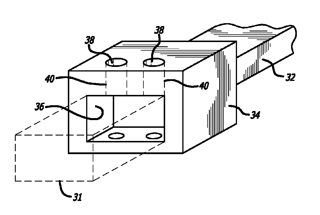
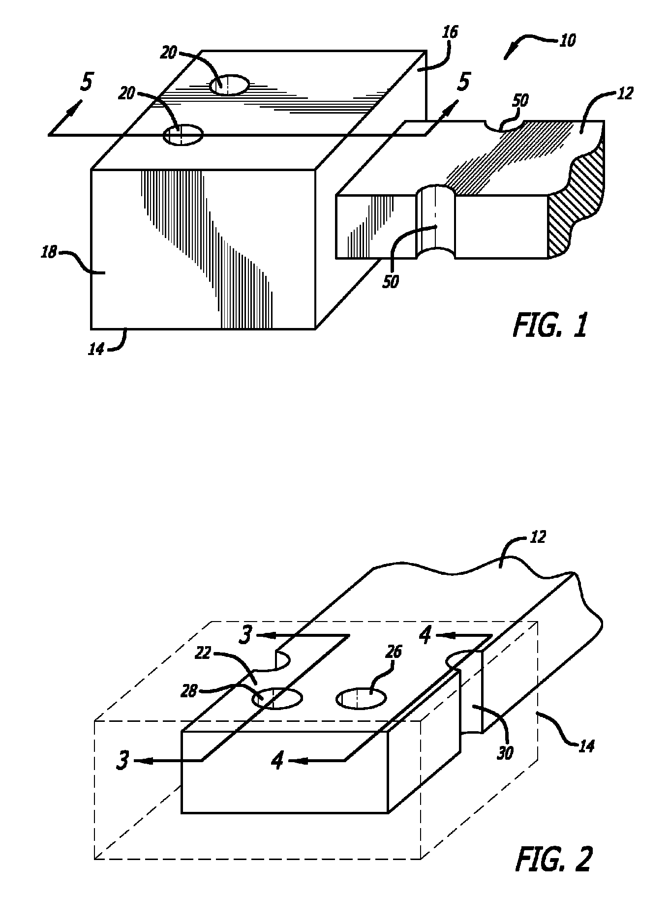
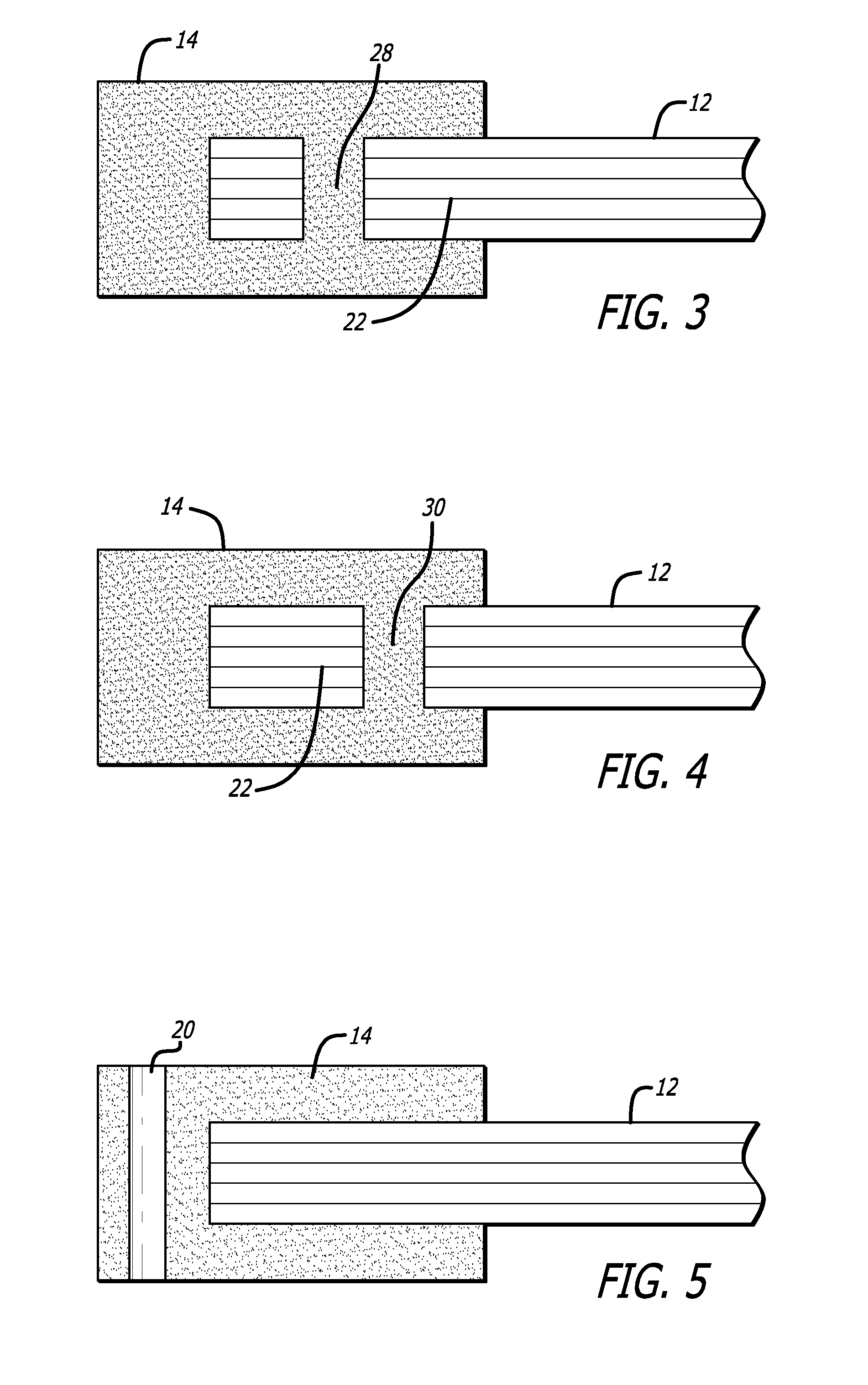
[0024]An exemplary composite structure in accordance with the present invention is shown generally at 10 in FIG. 1. The composite structure 10 includes a load-bearing element 12 and a connection element 14. The connection element of 14 includes a first portion 16 which is molded over the load-bearing element 12. The connection element 14 also includes a second portion 18 which includes holes 20 for connecting composite structure 10 to a support structure or body of the aircraft. Exemplary load-bearing elements include wing spars, propeller blades, struts, floor beams, various links including blocker door links, frames, intercostals, beams, skins, panels, jet engine blades and vanes including outer guide vanes and fan blades.

[0025]As shown in the FIG. 2, the load-bearing element 12 includes an attachment portion 22 over which the connection element (shown in phantom) is molded. Bond-enhancement surfaces are added to the attachment portion 22 in order to provide an increase in the sur...


PUM

PropertyMeasurementUnit
thicknessaaaaaaaaaa
thicknessaaaaaaaaaa
lengthaaaaaaaaaa

Abstract

A load-bearing composite structure for connection to a support body or structure. The load-bearing structure includes a load-bearing element that is made up of continuous reinforcing fibers and a resin matrix. The load-bearing element has an attachment portion for connection to the support body. The load-bearing composite structure further includes a connection element that is formed using a molding material which is composed of discontinuous fibers and a resin matrix. The molding material is molded over the surface of the attachment portion of the load-bearing element.

Description

BACKGROUND OF THE INVENTION[0001]1. Field of the Invention[0002]The present invention relates generally to composite structures that are used in load-bearing applications. More particularly, the present invention is directed to reinforcing the portion of the load-bearing composite structure that is connected to the body or sub-structure that also participates in carrying the load.[0003]2. Description of Related Art[0004]Composite materials typically include fibers and a resin matrix as the two principal components. Composite materials typically have a rather high strength to weight ratio. As a result, composite materials are being used in demanding environments, such as in the field of aerospace where the high strength and relatively light weight of composite parts are of particular importance.[0005]The fibers used in many load-bearing composite structures or elements are unidirectional and continuous. Such unidirectional fibers are particularly useful when the load-bearing structur...

Claims


Application Information

Patent Timeline
Patent Type & Authority Patents(United States)
IPC IPC(8): B32B3/24B29C69/00B29C70/10B29C70/84B29C70/76B29C70/54B29C70/12B29C70/06B29C70/20B29C70/16B29C70/08B29C70/22B29C70/88B29C70/74B29C70/68
CPCB29C70/545B29C69/001B29C70/68B29C70/745B29C70/84B29C69/00B29C70/081B29C70/088B29C70/10B29C70/12B29C70/16B29C70/20B29C70/682B29C70/74B29C70/742B29C70/76B29C70/763B29C70/88Y02T50/433Y10T29/49826Y10T428/17Y10T428/19Y10T428/24322Y10T428/24339Y10T428/24347Y10T428/24777Y10T428/24994Y10T428/24995Y10T428/249923Y10T428/249942Y10T428/249945Y02T50/40
Inventor BOURSIER, BRUNO
Owner HEXCEL
Learn More