Adjustable lever arm capo

a lever arm and capo technology, applied in the field of capo, can solve the problems of increasing the difficulty of adjustment, reducing the lateral and shear load of the adjuster screw and the linkage, and reducing so as to reduce the stress of the lever arm and the capo, the effect of compact and integrated assembly and reduced lateral load

Active Publication Date: 2011-05-10
C7TH
View PDF30 Cites 14 Cited by
  • Summary
  • Abstract
  • Description
  • Claims
  • Application Information

AI Technical Summary

Benefits of technology

[0014]This arrangement ensures that the lower arm and so capo, is held open making fitting of the capo easier. It also restricts movement of the lower arm to prevent tangling when not in use and fitted to the neck.
[0017]With the line of action of the adjuster mechanism extending through the pivotal attachment of the lever arm to the side arm the lateral loads on the adjuster mechanism are reduced and stresses with the lever arm and capo are reduced. In addition such an arrangement provides a more compact and integrated assembly.

Problems solved by technology

Despite the commercial success of the capo described in U.S. Pat. No. 4,250,790 over a number of years there are problems which have not to date, despite the time over which this capo has been available, been recognised or addressed and which have generally been overlooked.
In particular this type of capo is in fact relatively difficult to apply and generally needs two hands to fit to an instrument.
In addition the arms when the capo is not in use and attached to the instrument are prone to dangle and freely pivot and flap about preventing easy application to the guitar neck.
Furthermore the adjuster screw and linkages are subject to various lateral and shear loads.
This induces stresses within the assembly and also in relation to lateral loads on the adjuster screw increase the friction on the threads making adjustment more difficult.
U.S. Pat. No. 360,612, U.S. Pat. No. 468,193, and U.S. Pat. No. 4,149,443 which again date back over a number of years do not include suitable adjustment arrangements to accommodate different sizes of neck while achieving positive locking.
In relation to U.S. Pat. No. 468,193 and US 2008 / 0168882 locking is in particular achieved by a spring load such that it is not positively locked and the locking and load is less than ideal such that the strings may not be sufficiently clamped to give a crisp note, and / or the capo may become dislodged.

Method used


Image

  • Adjustable lever arm capo
  • Adjustable lever arm capo
  • Adjustable lever arm capo

Examples


Embodiment Construction

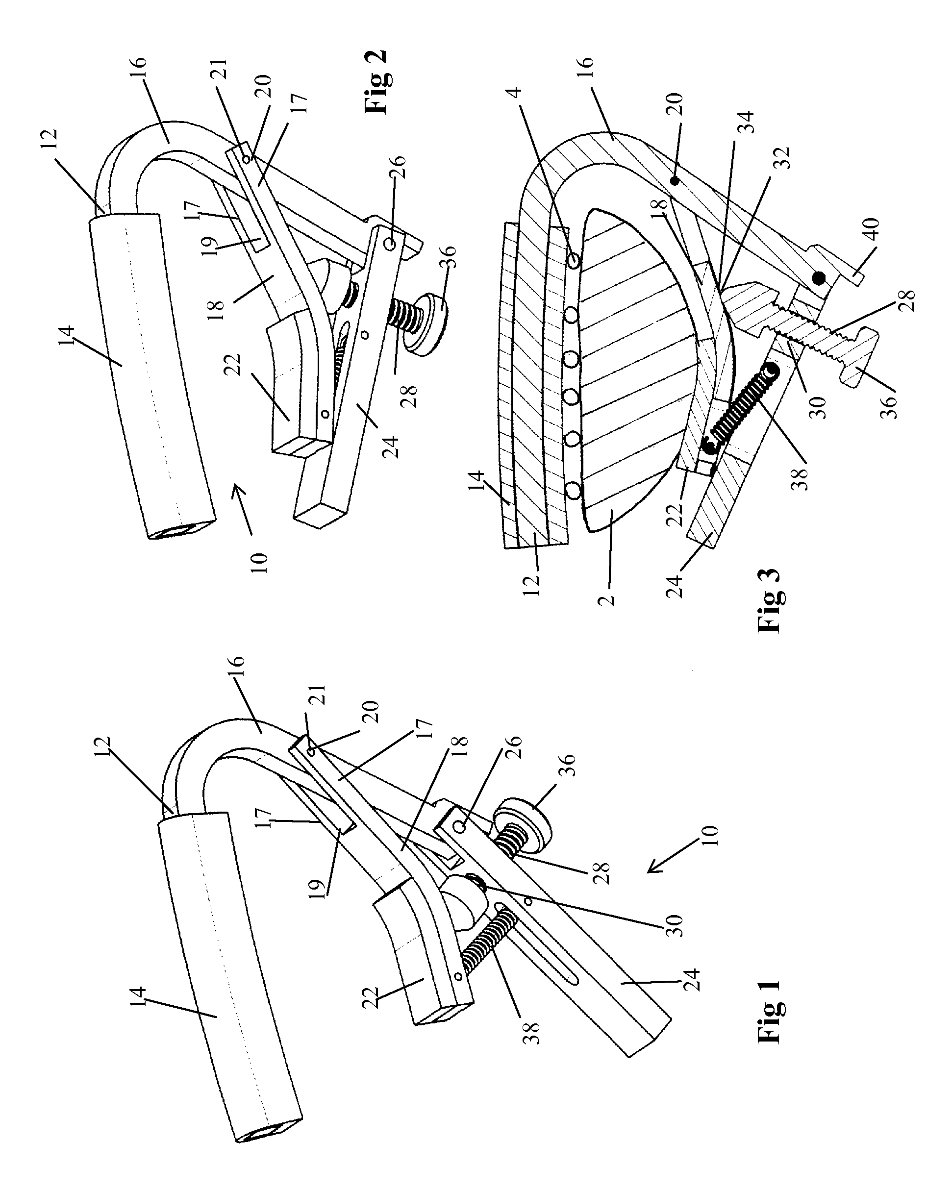
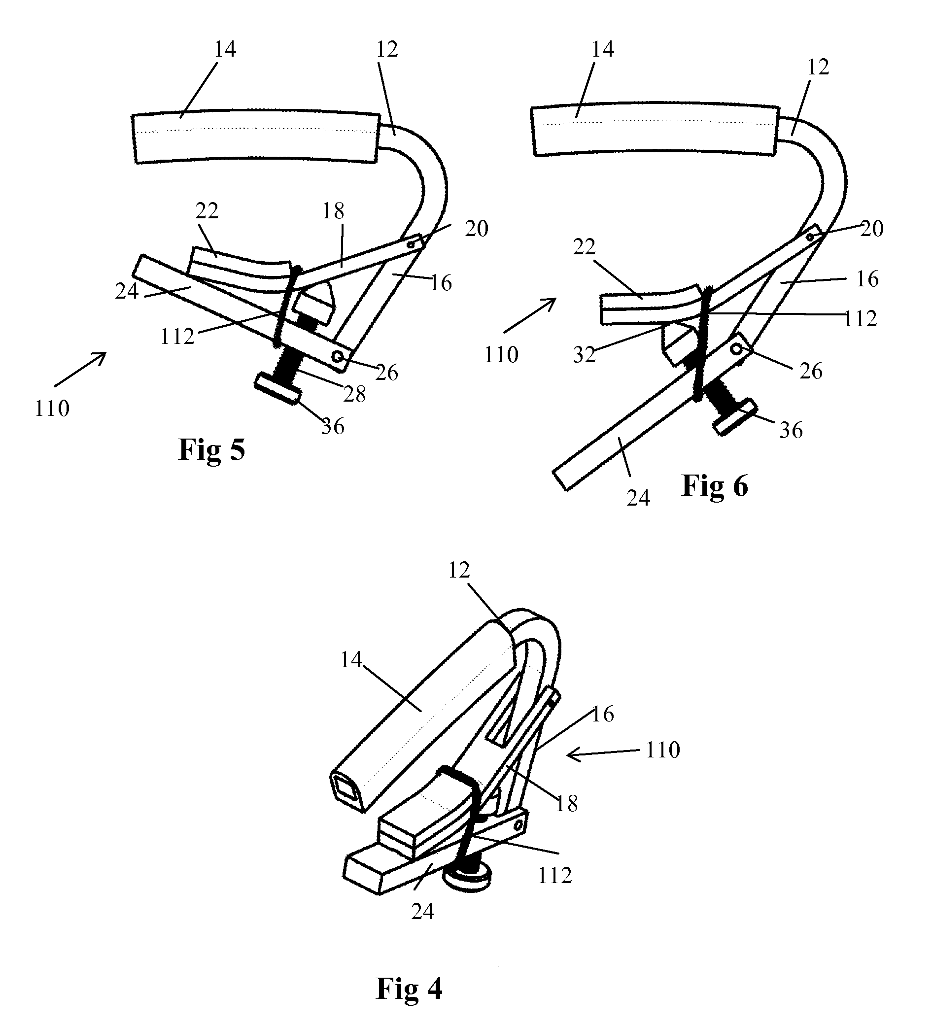
[0036]In the following description of the invention, certain terminology will be used for the purpose of reference only, and are not intended to be limiting. Terms such as “upper”, “lower”, “above”, “below”, “rightward”, “leftward”, “clockwise”, and “counter clockwise” refer to directions in the drawings to which reference is made. Terms such as “inward” and “outward” refer to directions toward and away from, respectively, the geometric centre of the component described. Terms such as “front”, “rear”, “side”, “left side”, “right side”, “top”, “bottom”, “horizontal”, and “vertical” describe the orientation of portions of the component within a consistent but arbitrary frame of reference which is made clear by reference to the text and the associated drawings describing the component under discussion. Such terminology will include the words specifically mentioned above, derivatives thereof, and words of similar import.

[0037]Referring to FIGS. 1 to 3, a capo 10 according to a first emb...


PUM


Abstract

A capo (10) for use with a stringed instrument comprises a top arm (12), lower arm (16) and a lever arm (24). The top arm (12) is adapted to extend across a fingerboard of the instrument above the strings (4), and a side arm is connected and extending at an angle to the top arm and arranged to extend generally laterally of the neck (2) of the instrument. The lower arm (18) has one end pivotally attached to the side arm (16) at a lower arm pivot (20) and is adapted to abut against the back of the neck of the instrument when in a closed position. The lever arm has one end pivotally attached to the side arm (16) at a pivot (26) spaced from the lower arm pivot (20). The capo further includes an adjuster mechanism (28, 334) that extends and projects an adjustable amount from the lever arm (24) and has an end tip (32) which bears against the lower arm (24).

Description

CROSS-REFERENCE TO RELATED APPLICATIONS[0001]This application claims foreign priority benefits under 35 U.S.C. §119(a)-(d) to GB 0823215.9, filed Dec. 19, 2008, which is hereby incorporated by reference in its entirety.BACKGROUND[0002]1. Field[0003]The present invention relates to a capo for a stringed musical instrument, in particular to improvements to lever arm type capos.[0004]2. Background Art[0005]A capo, sometimes variously termed a capodastro, capodaster, capo tasto or cejilla, is a well-known device used with a stringed instrument, for example a guitar or banjo, which has a neck and a set of strings extending along the length of the neck. The capo, when applied, serves to clamp the strings against the fingerboard provided along the neck, and in particular against one of the number of fret bars disposed along the length of the fingerboard, to reduce the effective length of the strings and therefore adjust the pitch produced by the strings.[0006]A large number of different ca...

Claims


Application Information

Patent Timeline
Patent Type & Authority Patents(United States)
IPC IPC(8): G10D13/02
CPCG10D3/043G10D3/053
Inventor CAMPLING, NICHOLAS JOHN
Owner C7TH
Why Eureka
Try Eureka