
Method and system for re-arranging a display

a display and display technology, applied in the field of rearranging a display, can solve the problems of limited display space, cluttered desktop, and no one truly optimizes the desktop space available, and achieve the effect of improving the display

Inactive Publication Date: 2011-05-10
IBM CORP
View PDF11 Cites 53 Cited by
  • Summary
  • Abstract
  • Description
  • Claims
  • Application Information

AI Technical Summary

Benefits of technology

[0004]The aim of the present invention is to provide an improved display.
[0006]By prioritizing the items available to display (based on predefined user preferences), items can be matched up with appropriate available grid units dynamically, and potentially removed from the display entirely when no suitable space is left for allocation. This has the advantage that the user simply needs to move the window(s) that he is interested in, and the desktop will dynamically bring the most relevant things into available window slots. This minimizes the time required to access functions.

Problems solved by technology

Graphical User Interfaces (GUIs) are popular but limited display space can mean a cluttered desktop.
All of these systems have their benefits, but none truly optimizes the desktop space available.
None of the solutions to desktop limitations applies easily to augmented reality displays.
Simply stated, the problem is providing the best selection of data in a limited space, be that a monitor display, or a heads up display (HUD) imposed on a field of vision.

Method used


Image

  • Method and system for re-arranging a display
  • Method and system for re-arranging a display
  • Method and system for re-arranging a display

Examples


first embodiment

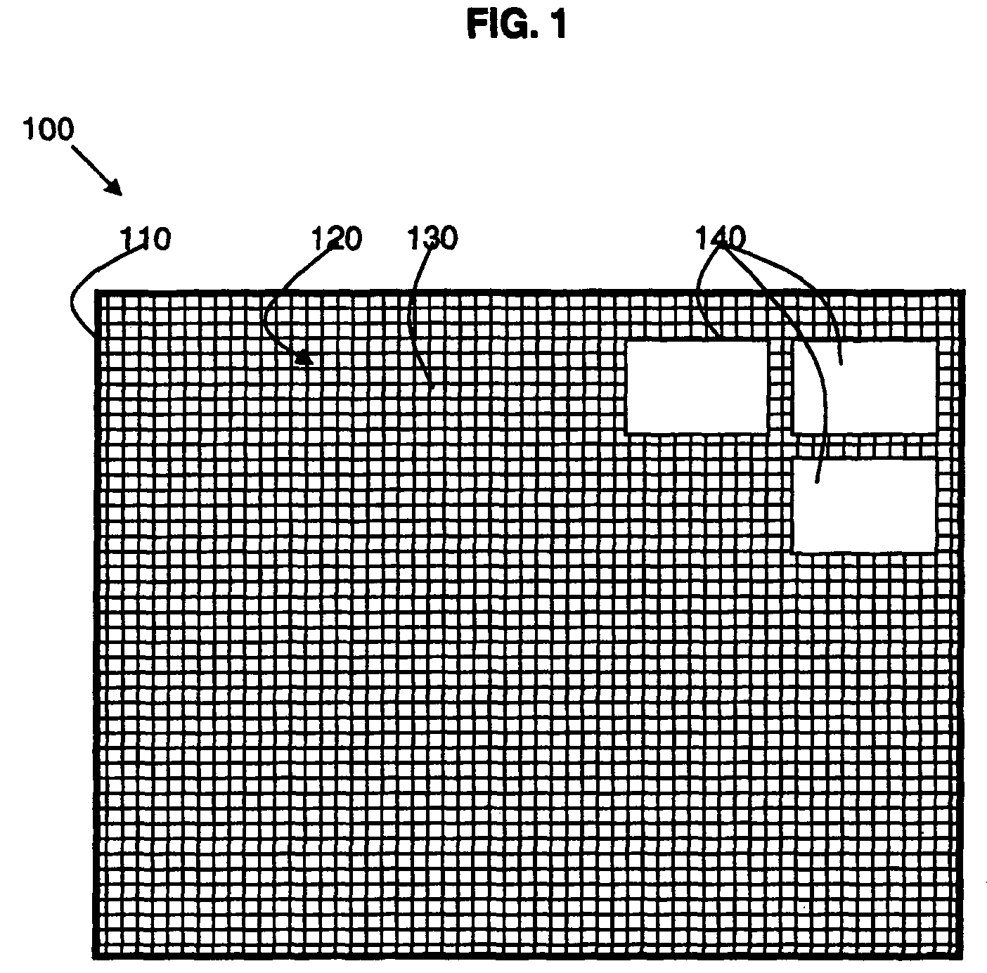
[0034]The first embodiment is a GUI of a computer system in which the viewable area 110 is a computer display such as a desktop or monitor screen. Data in the viewable area 110 is determined by the currently used applications. The display items 130 may be icons for other applications, other non-current windows, system preferences and parameters, etc.

second embodiment

[0035]The second embodiment is a HUD for use in a vehicle in which information is displayed in the field of view of the driver of the vehicle. The viewable area 110 is the field of view and the data in the viewable area 110 is the view seen by the driver of the road and surrounding objects. The display items 130 which are displayed in the HUD superimposed on the driver's field of view may be driving control parameters, direction information, etc.

third embodiment

[0036]The third embodiment is a game system in which the viewable area 110 is the game display and the data in the viewable area is the scene of the game. The display items may be in the form of control parameters, information regarding the score, the characters, etc.

[0037]All three embodiments the system can be broken into the same processing steps, as follows:

[0038]1. Identify the data in the viewable area in a form the computer understands;

[0039]2. Use an expert system with heuristic rules relevant to the application to rate:[0040]a. the importance of seeing certain parts of the viewable area, and[0041]b. the display items that should be displayed;

[0042]3. Place as many of the available display items as there is space for;

[0043]4. Repeat at a suitable refresh rate for the system or when the data in the viewable area changes.

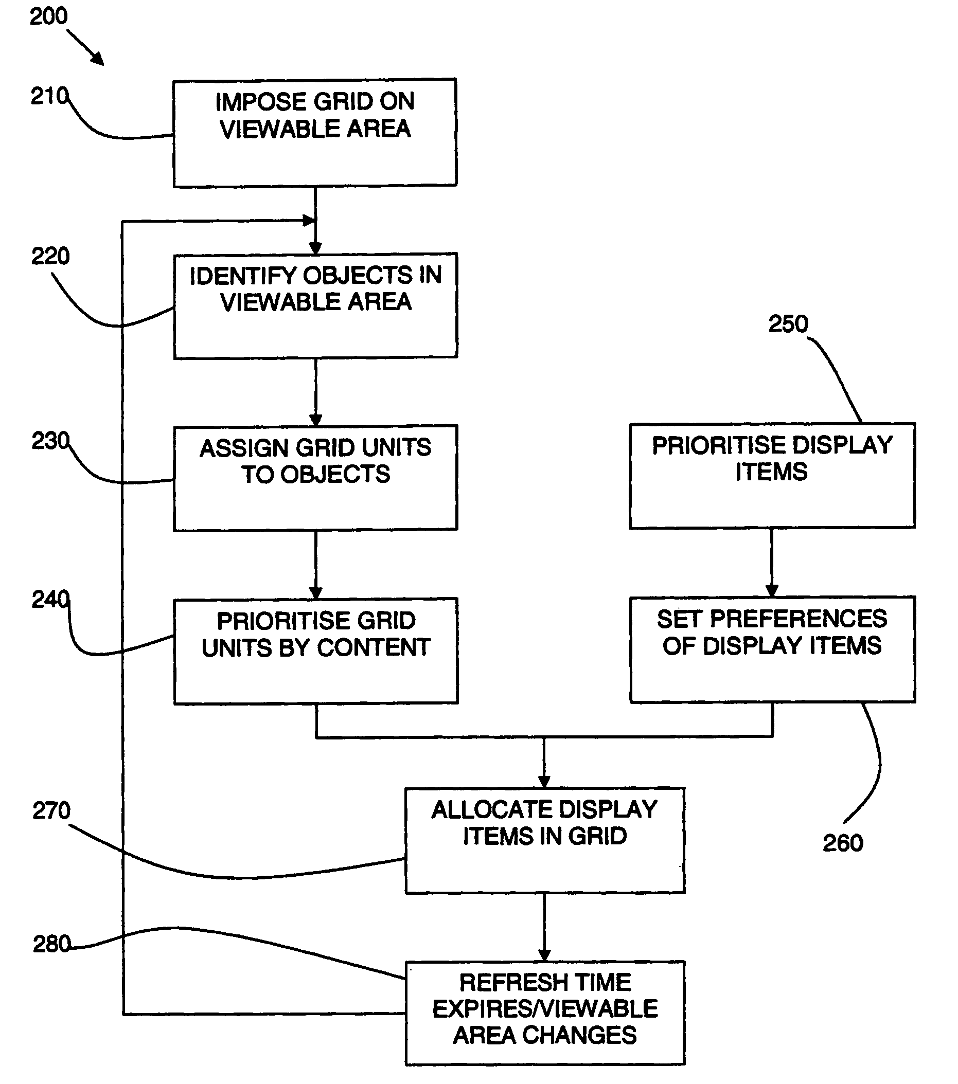
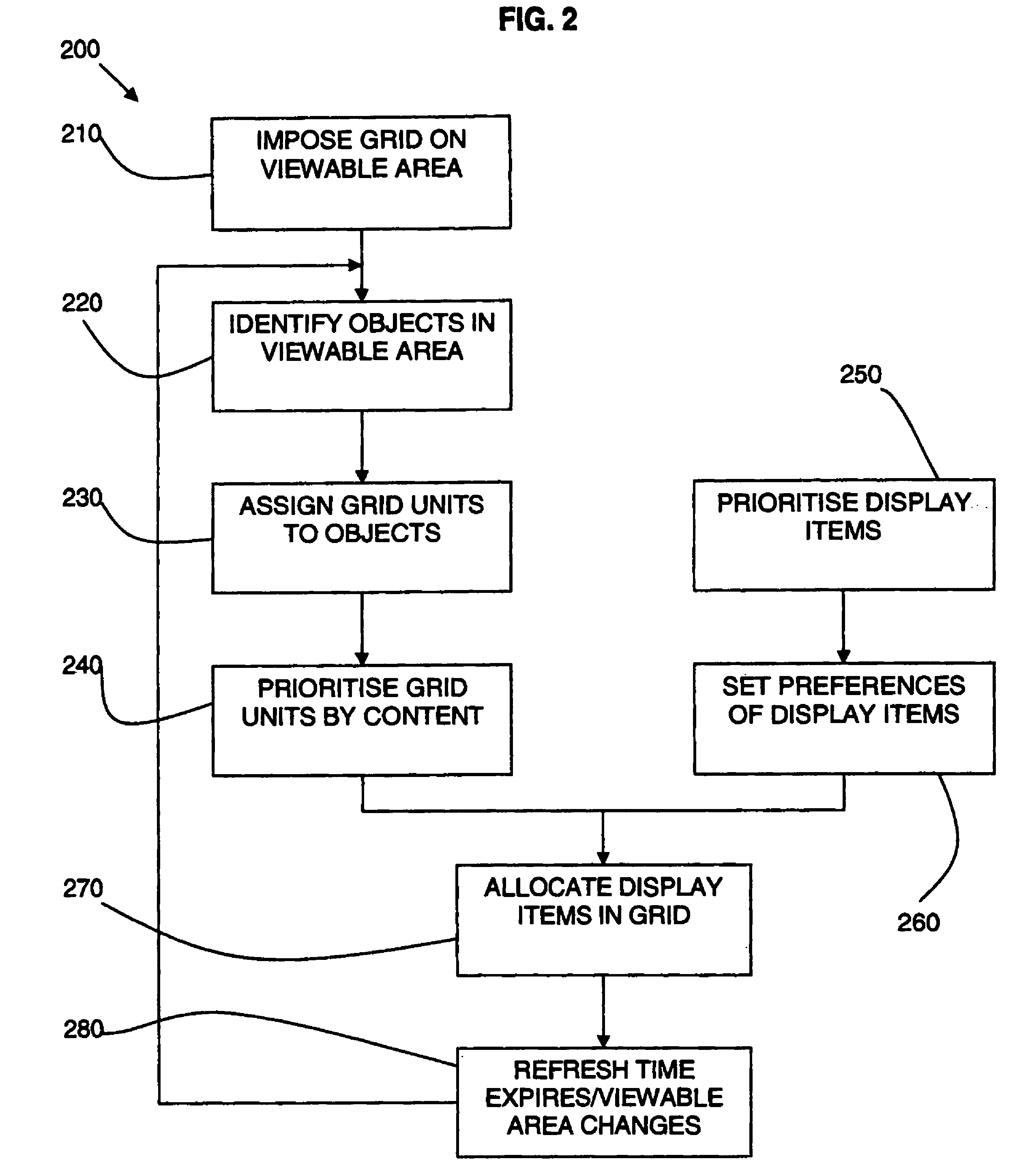
[0044]Referring to FIG. 2, the method or process of the display system is shown in the form of a flow diagram 200. In the first step 210, a grid is imposed on...


PUM


Abstract

A method and system are described for re-arranging a display in a viewable area. The method comprises dividing the viewable area into units; determining the contents of units of the viewable area; prioritizing the availability of the units by content; and allocating one or more display items in the prioritized available units. A plurality of display items is provided and the display items are allocated according to a determined order which may depend on one or more of a user preference, the contents of the viewable area, the activity of the user, and environmental parameters.

Description

BACKGROUND[0001]This invention relates to the field of re-arranging a display in a viewable area. In particular, this invention relates to re-arranging a display in response to dynamic feedback.[0002]Human interaction with digital displays is subject to constant attempts to improve. Graphical User Interfaces (GUIs) are popular but limited display space can mean a cluttered desktop. Solutions to desktop limitations include simple tool bars showing open windows that allow you to switch between active tasks, the ability to tile windows, and more recently Mac OS X (trade marks of Apple Computer, Inc.) have provided a feature that allows the temporary tiling of windows for tasks for the duration of a key press, snapping back to previous arrangement when the key is released. All of these systems have their benefits, but none truly optimizes the desktop space available.[0003]In the world of augmented reality in which a computer display is overlaid on the real world, there is the issue of a...

Claims


Application Information

Patent Timeline
Patent Type & Authority Patents(United States)
IPC IPC(8): G09G5/00G06F3/0482
CPCG06F3/0482
Inventor WOULD, DANIEL E.CLEE, SCOTT J.MASTERS, PETER B.
Owner IBM CORP
Learn More