Vacuum cleaning tool and method for its operation

a vacuum cleaning and vacuum technology, applied in the direction of mechanical suction control, suction nozzle, suction filter, etc., can solve the problems of insufficient cleaning results and the inability of the operator to adjust the optimal power of the turbine during operation, and achieve the effect of excellent adjustment of the drive power

Inactive Publication Date: 2011-05-17
DUPRO AG
View PDF2 Cites 13 Cited by
  • Summary
  • Abstract
  • Description
  • Claims
  • Application Information

AI Technical Summary

Benefits of technology

[0004]It is an object of the present invention to provide a vacuum cleaning tool of the aforementioned kind with which an excellent adjustment of the drive power can be achieved.

Problems solved by technology

However, it has been found that the operator during operation often does not carry out an optimal adjustment of the turbine power.
The adjustment of the turbine power to different floor coverings is often not done at all or not done to a satisfactory degree so that an insufficient cleaning result may be achieved.

Method used


Image

  • Vacuum cleaning tool and method for its operation
  • Vacuum cleaning tool and method for its operation
  • Vacuum cleaning tool and method for its operation

Examples


Embodiment Construction

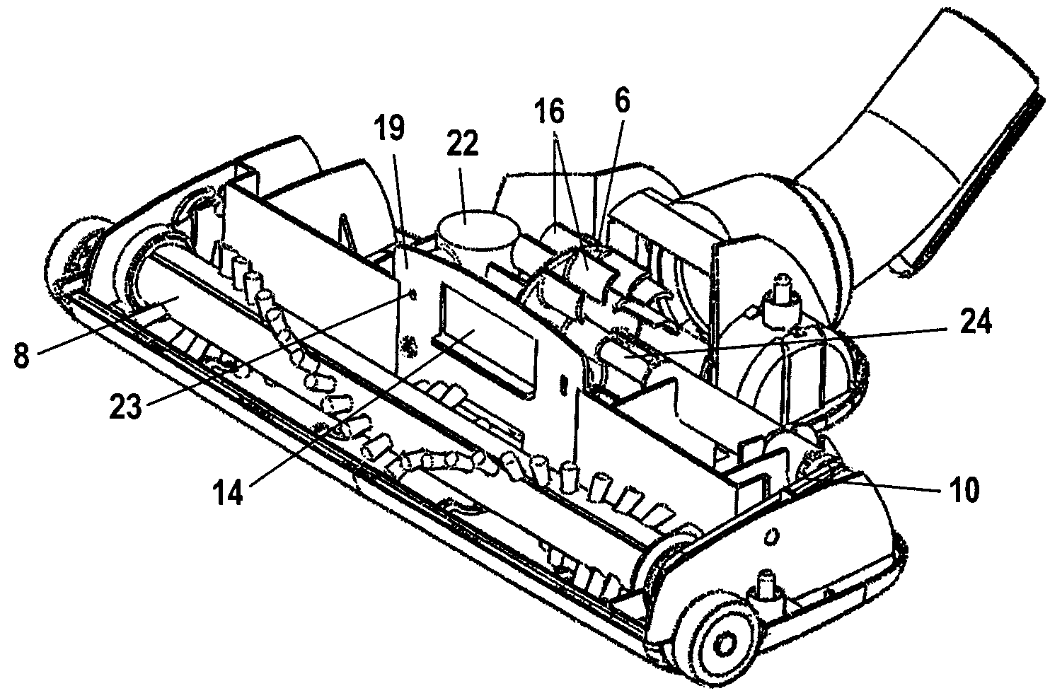
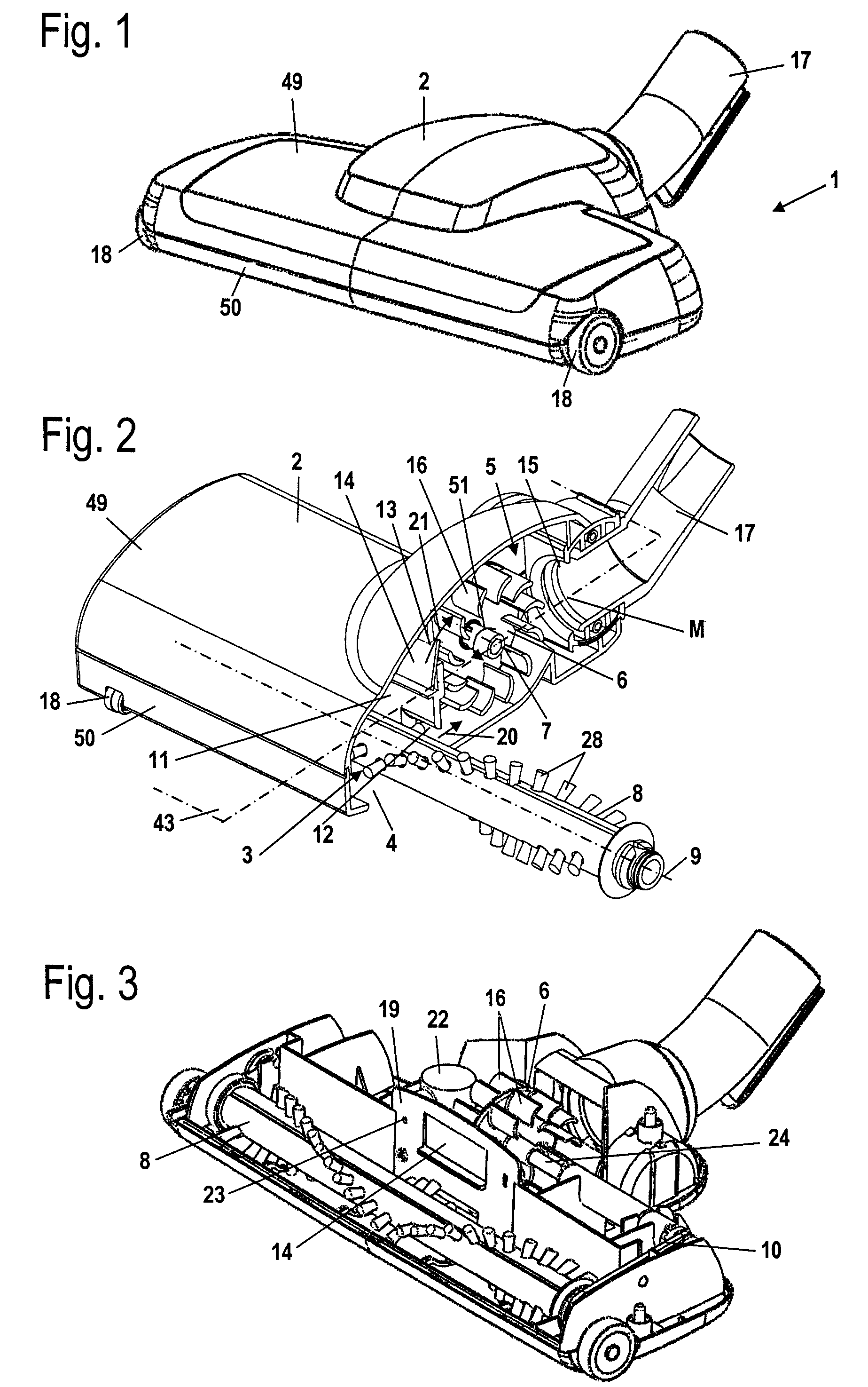
[0036]The vacuum cleaning tool 1 illustrated in FIG. 1 has a housing 2 that is comprised of an upper housing shell 49 and a lower housing shell 50. Two front wheels 18 are rotatably supported on the housing 2. A connecting socket 17 for connecting the vacuum cleaning tool 1 to a vacuum device of a vacuum cleaning device is arranged on the housing 2 of the vacuum cleaning tool 1.

[0037]In FIG. 2, the vacuum cleaning tool 1 is shown in a section view. The front wheel 18, as shown in FIG. 2, can also be arranged at the front side of the housing 2. In the lower housing shell 50, a suction opening 4 is provided that extends across the entire width of the vacuum cleaning tool 1 transversely to the working direction. The suction opening 4 is slot-shaped. Above the suction opening 4 a cleaning tool, i.e., a brush roller 8, is supported to be rotatable about axis of rotation 9. A plurality of bristles 28 are secured on the brush roller 8. The housing 2 is divided transversely to the working d...


PUM


Abstract

A vacuum cleaning tool has a housing having a connecting socket for effecting flow communication to a vacuum device of a vacuum cleaning device. The housing has a suction opening through which a working air flow enters the housing. The housing has an outlet opening through which the working air flow exits from the housing. A cleaning tool is rotatably supported in the housing. An air turbine is rotatably supported in a turbine chamber of the housing and drives the cleaning tool in rotation. A control device controls the drive power for driving the cleaning tool based on a pressure existing in the vacuum cleaning tool.

Description

BACKGROUND OF THE INVENTION[0001]The invention relates to a vacuum cleaning tool comprising a housing provided with: a connecting socket for flow communication with a vacuum device of a vacuum cleaning device; an intake opening through which the working air flow enters the housing; an outlet opening through which the working air flow exits from the housing; a cleaning tool that is rotatably supported in the housing; and an air turbine for rotatingly driving the cleaning tool, wherein the air turbine is supported rotatably in a turbine chamber. The invention further relates to a method for operating such a vacuum cleaning tool.[0002]U.S. Pat. No. 6,813,809 discloses a vacuum cleaning tool comprising an air turbine that rotatingly drives the cleaning tool. For different types of floor coverings different speeds of the cleaning tool are desirable. The speed of the cleaning tool varies also as a function of the vacuum power of the vacuum device. In the device of U.S. Pat. No. 6,813,809,...

Claims


Application Information

Patent Timeline
Patent Type & Authority Patents(United States)
IPC IPC(8): A47L9/14
CPCA47L9/04A47L9/0072
Inventor WORWAG, PETER
Owner DUPRO AG
Why Eureka
Try Eureka