Sprinkler having oscillating mechanism

a technology of oscillating mechanism and sprinkler, which is applied in the direction of spray nozzles, spraying apparatus, movable spraying apparatus, etc., can solve the problem of no control valve device to control the water flowing through the central shaft, and achieve smooth or swift flow out, smooth rotating or driving the sprinkler tube, and avoiding dead points

Inactive Publication Date: 2011-05-17
YUAN PIN IND
View PDF5 Cites 3 Cited by
  • Summary
  • Abstract
  • Description
  • Claims
  • Application Information

AI Technical Summary

Benefits of technology

[0009]The primary objective of the present invention is to provide a sprinkler including an oscillating mechanism for smoothly rotating or driving the sprinkler tube and for avoiding dead points to be occurred, and thus for allowing the water to smoothly or swiftly flow out of the sprinkler tube in various kinds of water spraying patterns.
[0013]The barrel and the shaft each include a first gear provided thereon, a paddle wheel is coupled to the barrel and the shaft for rotating the barrel and the shaft in different direction relative to the receptacle, the paddle wheel includes a pinion secured thereto and rotated in concert therewith, a reduction gearing engaged with the pinion and engaged with the first gear of the shaft, and at least one idle gear engaged between the first gear of the barrel and the reduction gearing for allowing the barrel and the shaft to be rotated in different direction relative to the receptacle by the paddle wheel.

Problems solved by technology

However, there is no control valve device to control the water flowing through the central shaft.

Method used


Image

  • Sprinkler having oscillating mechanism
  • Sprinkler having oscillating mechanism
  • Sprinkler having oscillating mechanism

Examples


Embodiment Construction

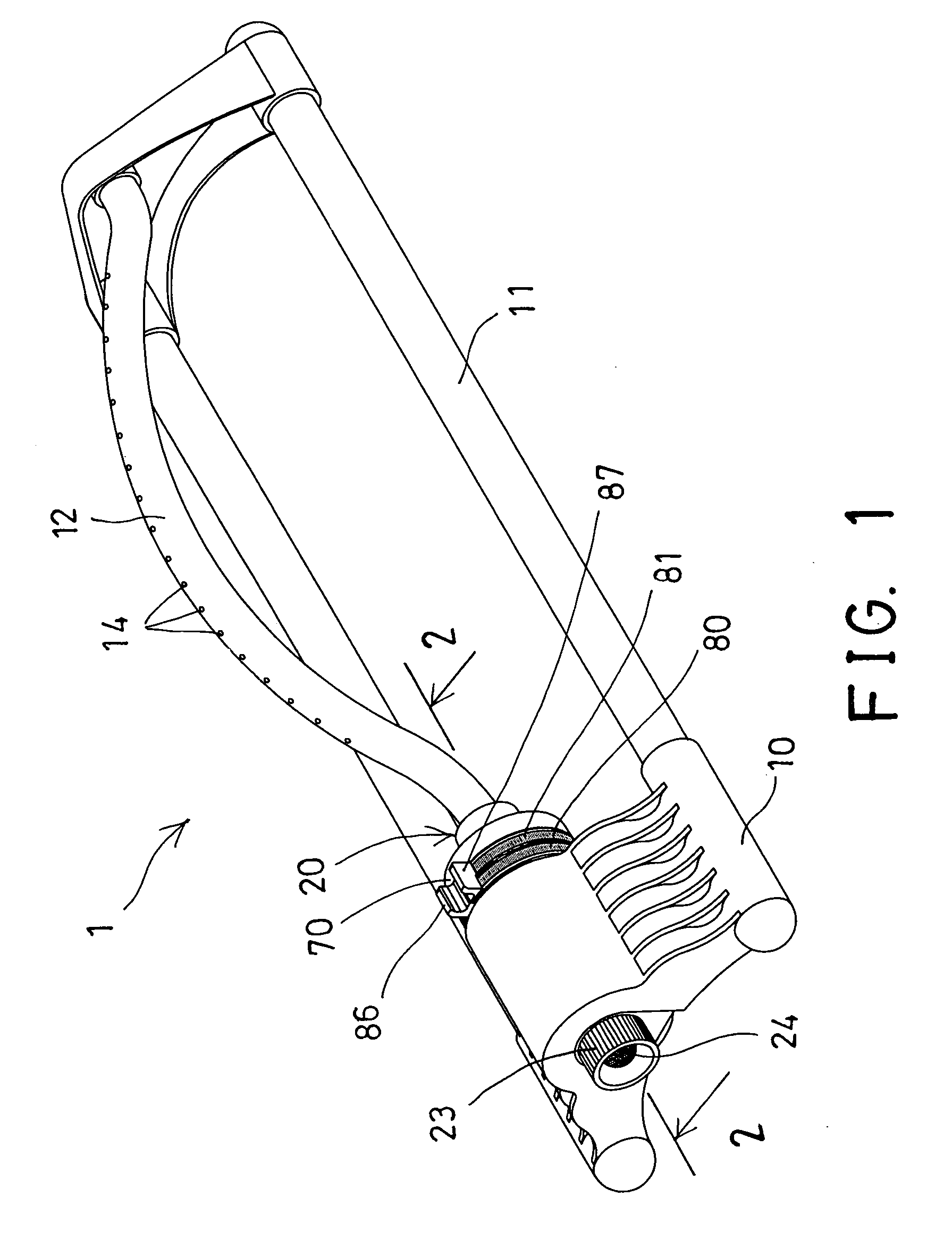
[0039]Referring to the drawings, and initially to FIG. 1, a sprinkler 1 in accordance with the present invention comprises a housing 10 attached or disposed on one side of a runner assembly or a base 11, for receiving and supporting an oscillating mechanism 20 therein, and a sprinkler tube 12 coupled to the oscillating mechanism 20 and / or rotatably or swingably supported or attached to the base 11, for allowing the sprinkler tube 12 to be rotated relative to the housing 10 or the base 11 by the oscillating mechanism 20. The sprinkler tube 12 includes a number of perforations 14 formed therein, for allowing water to flow out through the perforations 14 of the sprinkler tube 12.

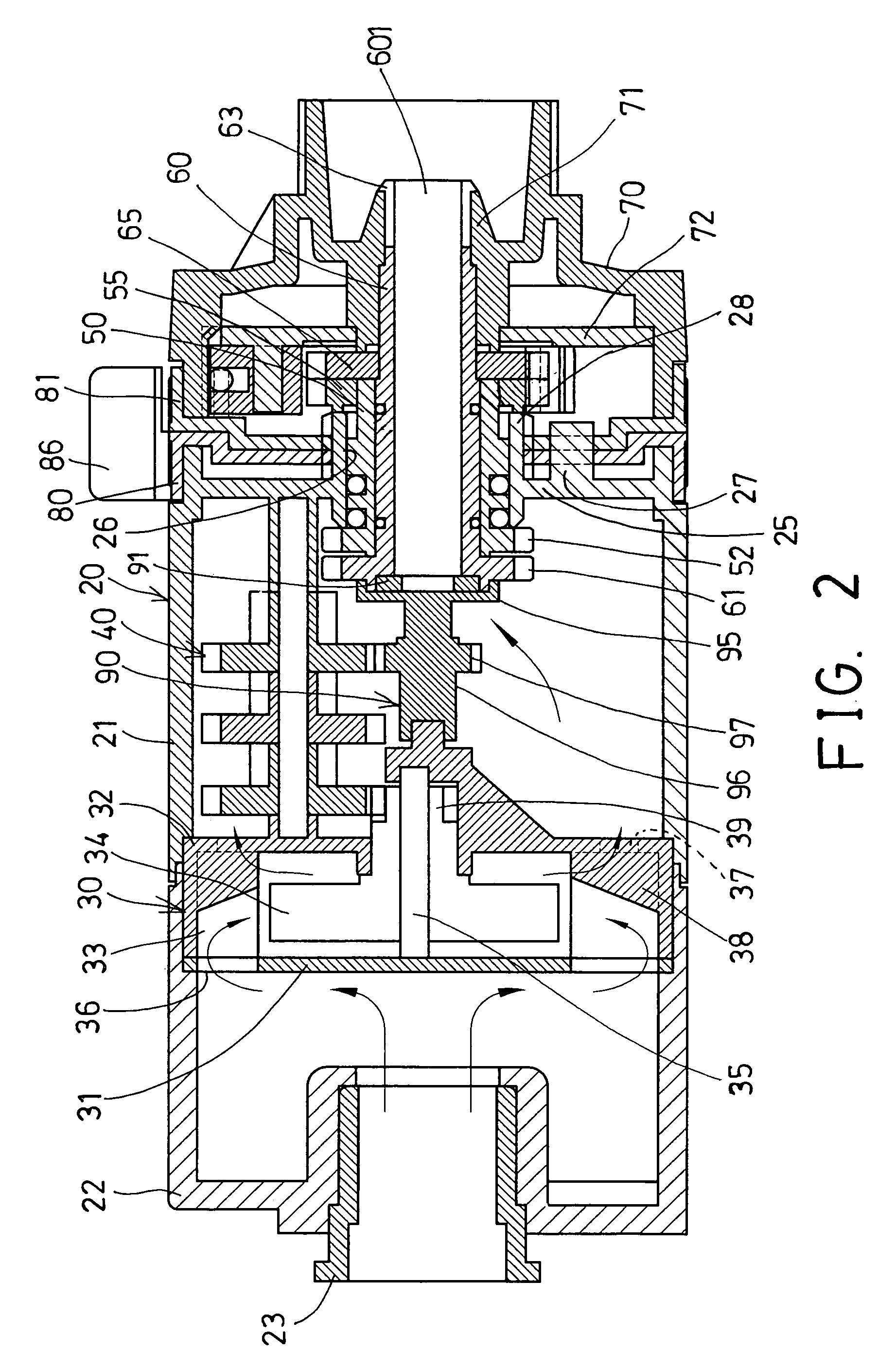
[0040]Referring next to FIGS. 2-4, the oscillating mechanism 20 includes a receptacle 21 disposed or received or secured within the housing 10, and having an extension or receptacle member 22 attached or secured to one side of the receptacle 21, the receptacle member 22 may also be formed integral with the rece...


PUM


Abstract

A sprinkler includes an oscillating mechanism having a receptacle for receiving a water, and a casing rotatably attached to the receptacle. A device may be used for swinging the casing relative to the receptacle in reciprocating action, to allow the water to smoothly or swiftly flow out of the sprinkler tube in various kinds of water spraying patterns. Two ratchet gears are rotatably received within the receptacle and rotated in different directions, a barrel and a shaft are rotatably received within the receptacle and rotated in different directions, and a valve controlling device may be used for controlling the water to flow through the shaft, such as to flow through the shaft intermittently.

Description

BACKGROUND OF THE INVENTION[0001]1. Field of the Invention[0002]The present invention relates to a sprinkler, and more particularly to a sprinkler having an oscillating mechanism for smoothly rotating or driving the sprinkler tube and having a control valve device to control the water flowing through a central shaft of the sprinkler.[0003]2. Description of the Prior Art[0004]Typical sprinklers comprise a sprinkler tube including one end coupled to a water reservoir for receiving the water from the water reservoir, and the other end having one or more openings for allowing the water to flow out of the sprinkler tube in various kinds of water spraying patterns, an impeller for rotating or swinging the sprinkler tube in reciprocating action, and having a heart-shaped cam member driven by a driving shaft, for engaging with a laterally extended pivot member, and thus for swinging the sprinkler tube in reciprocating action when the heart-shaped cam member is continuously rotated by the dr...

Claims


Application Information

Patent Timeline
Patent Type & Authority Patents(United States)
IPC IPC(8): B05B1/30
CPCB05B3/044B05B1/3026
Inventor HUANG, CHEN TUNG
Owner YUAN PIN IND
Why Eureka
Try Eureka