
Virtual root bridge

a virtual root bridge and root bridge technology, applied in the field of network topologies and network protocols, can solve the problems of cluster size (i, inherently limited to approximately, the size of an rstp network

Inactive Publication Date: 2011-05-17
TELEFON AB LM ERICSSON (PUBL)
View PDF25 Cites 35 Cited by
  • Summary
  • Abstract
  • Description
  • Claims
  • Application Information

AI Technical Summary

Benefits of technology

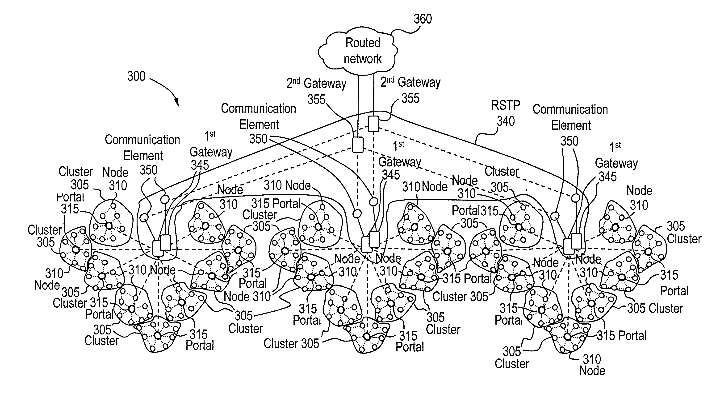
The present invention provides a network system and method for detecting the presence of other network nodes and communicating with them using a virtual root bridge protocol (VRBP). The network system includes a plurality of network clusters, each containing a plurality of nodes. Each network cluster includes a portal node that communicates with nodes within the cluster using a link that crosses a boundary of the cluster. The portal node is responsible for transmitting detection packets for detecting other portal nodes. The detection packets include a VRBP frame that identifies the network cluster to which the portal node belongs. Nodes within the network cluster use RSTP to communicate with the portal node. The network system can be a wireless mesh network or a hierarchical mesh network. The invention allows for efficient communication and detection of nodes in the network system.

Problems solved by technology

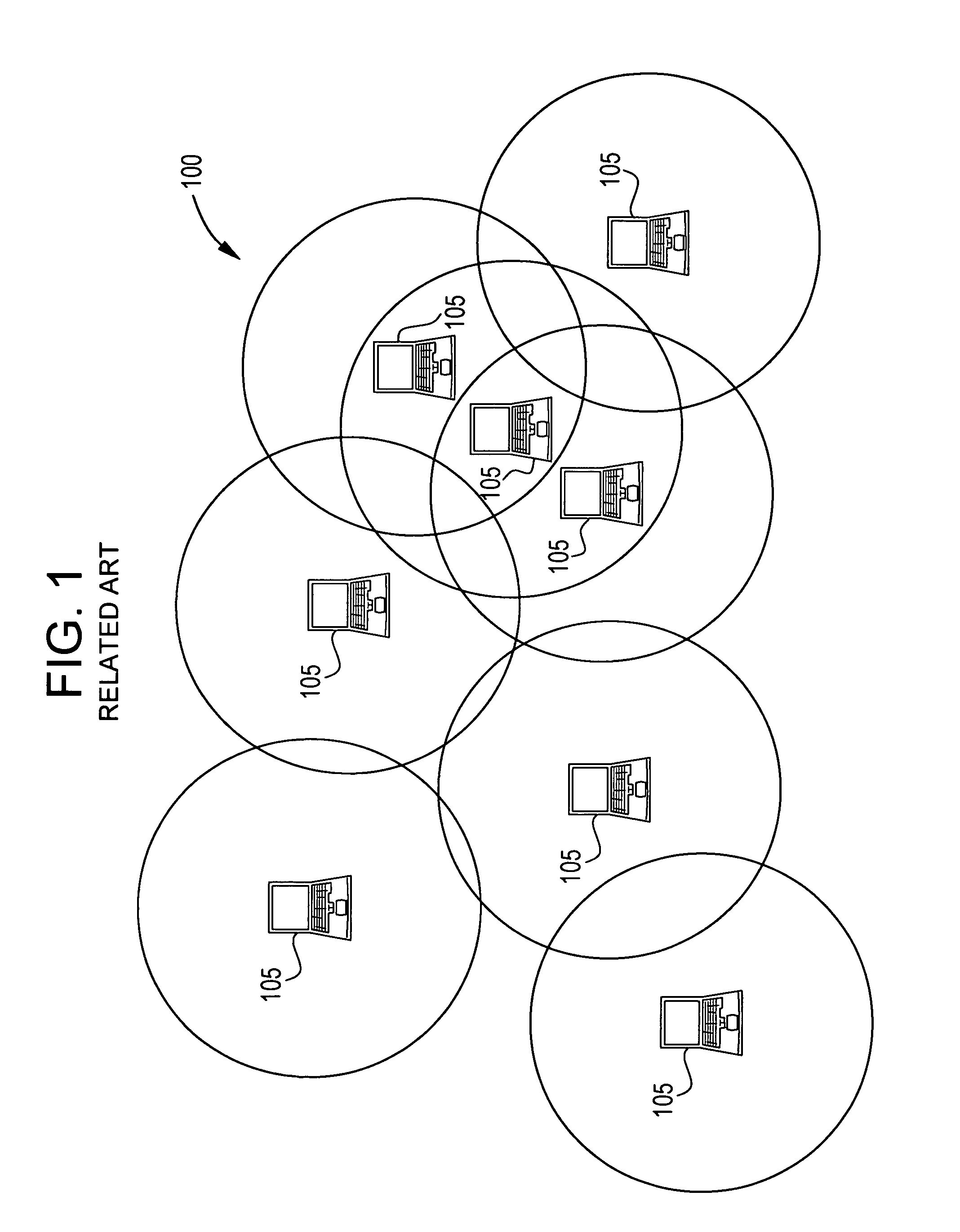
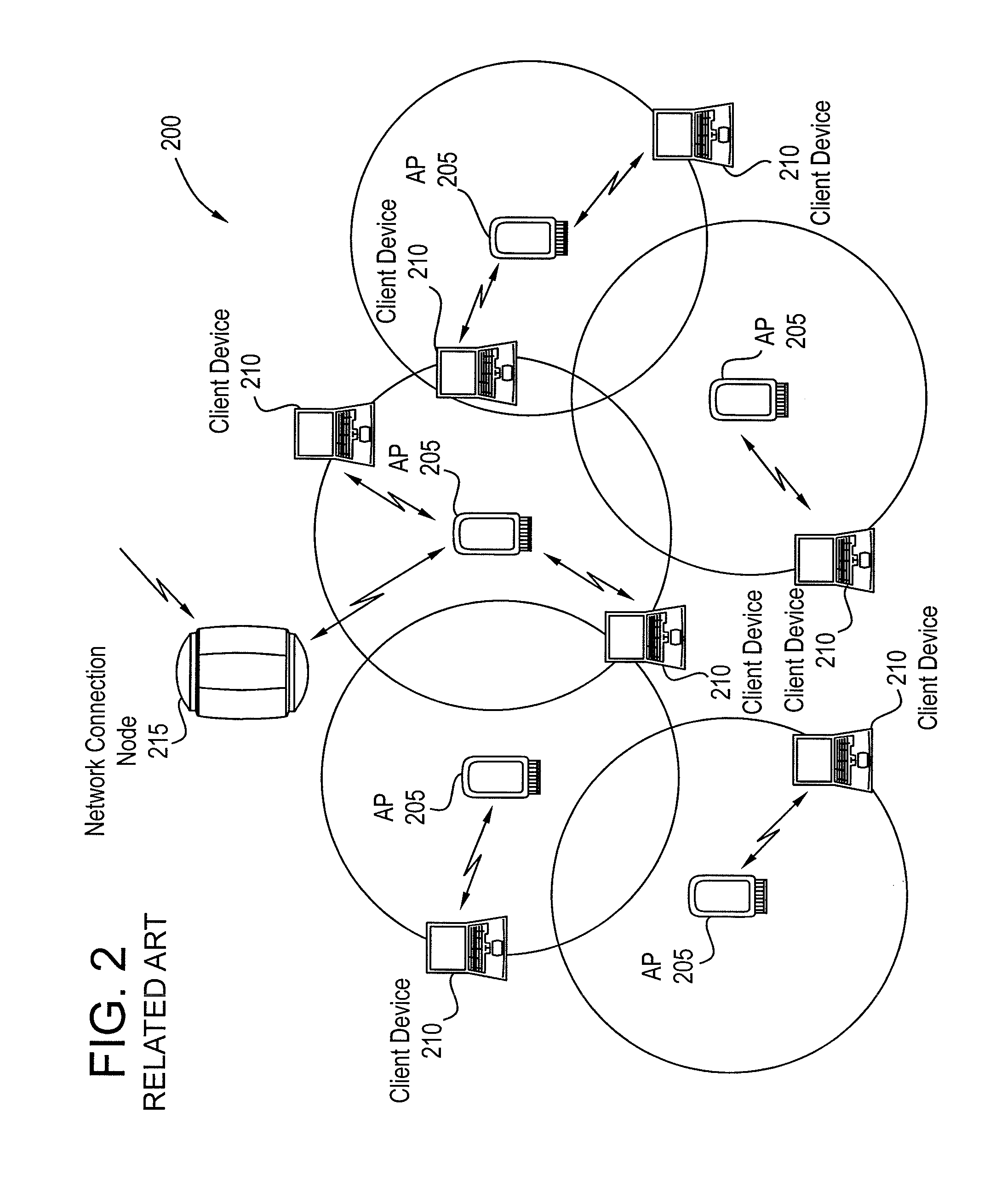
Furthermore, the cluster size (i.e., the number of nodes with M2M links to other nodes in the cluster) is inherently limited to approximately eight nodes.
It should be noted that conventional mesh network topologies generally assumes there is no such connection to an external network, even though such a network may be of limited usefulness.
One factor limiting the size of an RSTP network is the aging of root bridge information.
Such a limit is observed for any reasonable combination of link and node failures.
However, a wireless mesh network can require a lower hop limit, because the links are inherently less reliable than conventional wired links.
Such a scenario implies that the hop limit for the base network would be lower, which can severely limit the maximum allowable network size.
In sum, conventional RSTP is not a complete solution for determining paths through a large mesh network, because of scalability limits.
However, RSTP does not easily support such a type of partitioning.

Method used


Image

  • Virtual root bridge
  • Virtual root bridge
  • Virtual root bridge

Examples


Embodiment Construction

[0031]Exemplary embodiments of the present invention are directed to a virtual root bridge protocol (“VRBP”) for use in networks, such as, for example, mesh networks or the like. According to exemplary embodiments, the VRBP can support redundant links between two or more network clusters or instances of the network. A single Layer 2 network (of the Open System Interconnection (OSI) Model) can be subdivided into several network clusters or “instances,” with each instance comprised of several nodes. For example, if the Rapid Spanning Tree Protocol (RSTP) or the like is used for the path selection algorithm for the network, then each network cluster can be a RSTP instance. An inter-instance link occurs where links cross the boundary of a network cluster, such as a RSTP instance, while nodes with such links are referred to herein as “portal nodes.”

[0032]If there are redundant inter-instance links between, for example, two RSTP instances, then a loop can exist that may not be detected by...


PUM


Abstract

A network includes a plurality of network clusters. Each network cluster includes a plurality of nodes. At least one of the plurality of nodes includes a portal node. A portal node is a node with at least one link that crosses a boundary of the network cluster. Each portal node is configured to communicate detection packets for detecting the existence of other portal nodes within the network cluster. Each portal node is configured to communicate with nodes within the network cluster associated with the respective portal node to indicate that the respective portal node is a predetermined number of hops away from a virtual root bridge associated with the network cluster.

Description

BACKGROUND[0001]1. Field of the Invention[0002]The present invention relates to networks and network topologies. More particularly, the present invention relates to a network and a network protocol, referred to herein as the “virtual root bridge (VRBP) protocol,” that can support redundant links between two or more network clusters or instances of the network.[0003]2. Background Information[0004]A multipoint-to-multipoint (“M2M”) network is an alternative architecture that can trade off lower performance for lower cost as compared to, for example, the point-to-point (“P2P”) architecture that can used in networks. As compared to a P2P network, a M2M network includes characteristics such as, for example, the following: links are not pre-configured; links are dynamic rather than static; and links are less reliable. Due to such characteristics, the best choice of path through the M2M network may change more often. Additionally, it is possible that portions of the network can become, for...

Claims


Application Information

Patent Timeline
Patent Type & Authority Patents(United States)
IPC IPC(8): H04L12/28H04L69/14H04W40/32H04W48/08H04W92/02
CPCH04L45/00H04L69/14H04W40/32H04L45/20H04W48/08H04W92/02
Inventor EGLIN, MATTHEW GEORGEJOSLIN, JEFFRAYMENT, STEPHEN
Owner TELEFON AB LM ERICSSON (PUBL)
Learn More