Rotary-wing vehicle system

a rotary-wing vehicle and vehicle technology, applied in the field of flying apparatuses, can solve the problems of price-sensitive flying toys, and achieve the effects of improved yaw stabilization, great flying stability, and critical cost of materials

Inactive Publication Date: 2011-05-24
ZIMET NACHMAN +1
View PDF68 Cites 40 Cited by
  • Summary
  • Abstract
  • Description
  • Claims
  • Application Information

AI Technical Summary

Benefits of technology

[0008]The present invention provides an innovative rotary-wing apparatus that is aeronautically stable, easy to fly and control, very small in size, safe to fly and low cost to produce. In accordance with the present invention a rotary-wing flying apparatus innovative design eliminates the need for gyros and motion sensors, expensive actuators and movable parts, rotor blades with changeable attacking angle, nor a tail rotor. Consequently making it possible to be produced at a very low cost, thus enabling implementations such as toys and other low cost applications. In addition it consists of innovative safety features for the operator and its surroundings making it possible to fly a rotary-wing platform of the current invention even in doors.
[0009]Rotary-wing vehicle systems are well known and are being widely used for various mobile applications. The present invention diminishes at least some of the disadvantages associated with methods and solutions of very small helicopters that are designed for stability while maintaining minimal costs, a simple control, a high reliability, robustness and endurance and with no, or minimal need for tuning and adjustments.

Problems solved by technology

Unlike flying vehicles, flying toys are typically very price-sensitive.

Method used


Image

  • Rotary-wing vehicle system
  • Rotary-wing vehicle system
  • Rotary-wing vehicle system

Examples


Embodiment Construction

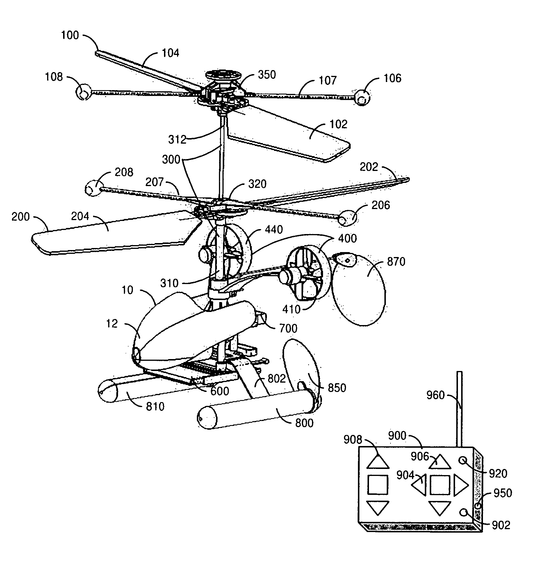
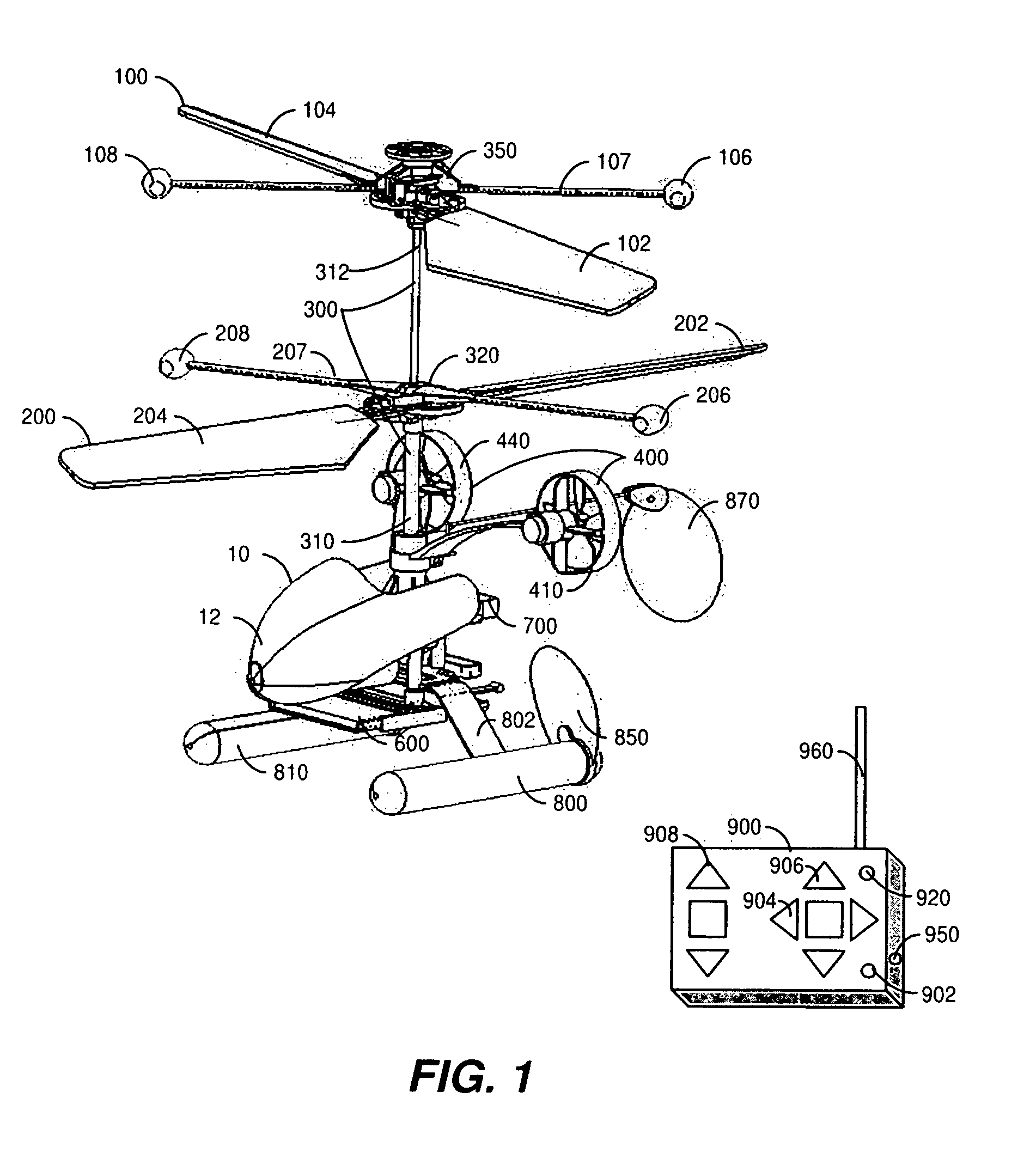
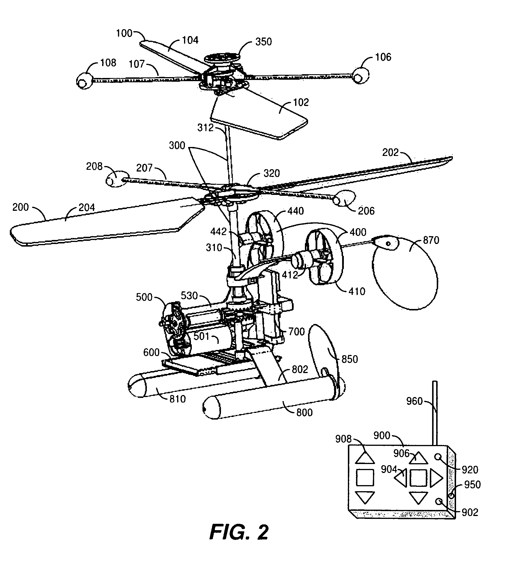
[0034]Reference is now made to FIGS. 1 and 2 which are simplified pictorial diagrams illustrating one preferred embodiment of the present invention, a rotary-wing flying apparatus operating in a plurality of applications. The illustrated embodiment of FIGS. 1 and 2 are presented in the context of flying toys, it is understood that this embodiment of the invention is not limited to toys and is equally applicable to other suitable types of small flying objects where cost, stability and ease of use are of importance.

[0035]FIG. 1 illustrates a front isometric view of a micro rotary-wing apparatus 10 of a preferred embodiment of the current invention.

[0036]A micro rotary-wing apparatus 10 consists of two sets of counter rotating blades, a lower rotor blades system 200 and the upper rotor blades system 100.

[0037]A main coaxial drive shaft 300 provides a rotating power to the two sets of counter rotating blades 100, 200. The main coaxial drive, shaft 300 consists of two parts: an outer mai...


PUM


Abstract

A rotary-wing apparatus that is aeronautically stable, easy to fly with a multidimensional control, small size, and safe to fly and low cost to produce. The rotary-wing apparatus includes a coaxial, counter rotating rotor drive providing lifting power with an inherent aeronautical stability; auxiliary propellers that face the direction of flight and are located on opposite sides of said coaxial rotary-wing apparatus and enable flying forwards, backwards and perform yawing. The rotary-wing coaxial helicopter toy is remotely controlled and safe to fly in doors and out doors, while performing exciting maneuvers even by untrained kids.

Description

RELATED APPLICATIONS[0001]This application is based on provisional application No. U.S. 60 / 624,941, filed on Nov. 5, 2004.FIELD OF THE INVENTION[0002]The present invention relates to flying apparatuses generally and more specifically to self-stabilizing rotating flying toys.BACKGROUND OF THE INVENTION[0003]The passion of flying has accompanied human beings from the early days of the humankind. The well-documented Helical Air Screw drawing of Leonardo Da Vinci in the fifteen-century was an important step towards a vertical take off, hovering and landing flying apparatus. It was only when a light weight powerful enough engine for powering rotating blades become available when Paul Cornu took off vertically in 1907. Vertical flights became easier and smoother when gyro control became available in mid-1940's and became common about a decade later.[0004]A helicopter typically has two rotor blades that are connected through a drive shaft to an engine. The air deflected downwards due to th...

Claims


Application Information

Patent Timeline
Patent Type & Authority Patents(United States)
IPC IPC(8): B64C27/82B64C27/10A63H27/133
CPCB64C27/10A63H27/12
Inventor ZIMET, NACHMAN
Owner ZIMET NACHMAN
Why Eureka
Try Eureka