
System and method for tracing rib posterior in chest CT volumes

a rib posterior and chest ct technology, applied in the field of 3d visualization of rib structures in medical computer-aided diagnosis systems, can solve the problems of large amount of digital data that is difficult and tedious to be interpreted merely by physicians, difficult to obtain good results from rib segmentation, vague gaps between ribs, etc., and achieves simple mathematical results and rapid computation

Inactive Publication Date: 2011-05-24
SIEMENS MEDICAL SOLUTIONS USA INC
View PDF12 Cites 4 Cited by
  • Summary
  • Abstract
  • Description
  • Claims
  • Application Information

AI Technical Summary

Benefits of technology

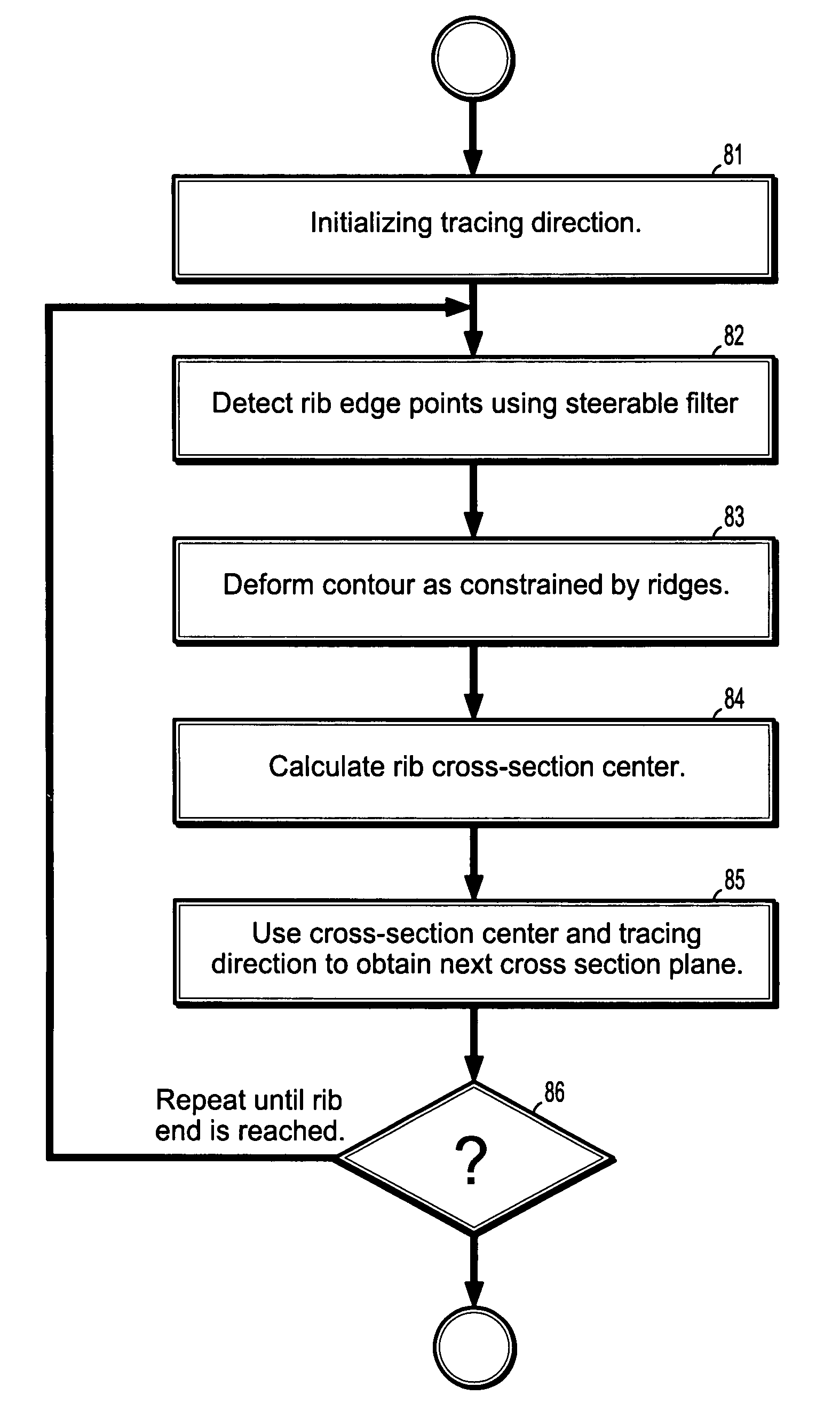
[0009]Exemplary embodiments of the invention as described herein generally include methods and systems for fast and robust tracing of rib posteriors that searches for a rib edge location by using the ridge as a constraint. As a follow-up to an edge-based rib tracing method of individual ribs in a CT volume, a method according to an embodiment of the invention completes the tracing by tracing into the rib posterior segments and stopping before the vertebrae. A method according to an embodiment of the invention uses a 2D ridge detector together with a deformable mode to locate rib edges. The tracing will stop at the end of rib posteriors. A chest CT volume is used as input. Starting from a seed point found by a seed-searching method, an edge-based tracing should be performed first. The edge-based tracing will stop at a certain point where another bone-like structure is present in the rib cross-section plane that is close to the rib bone. Then a method according to an embodiment of the invention takes over and continues tracing the posterior segments until the rib end. Since contour deformation according to an embodiment of the invention is performed with a small set sample points, the mathematics is simple and leads to rapid computation. The results can be used in rib labeling or 3D visualization in a diagnosis system. Also, the results can be combined with other applications, such as a 3D atlas of the thoracic cage, to serve as an efficient aid to physicians in the diagnosis of various bone diseases.
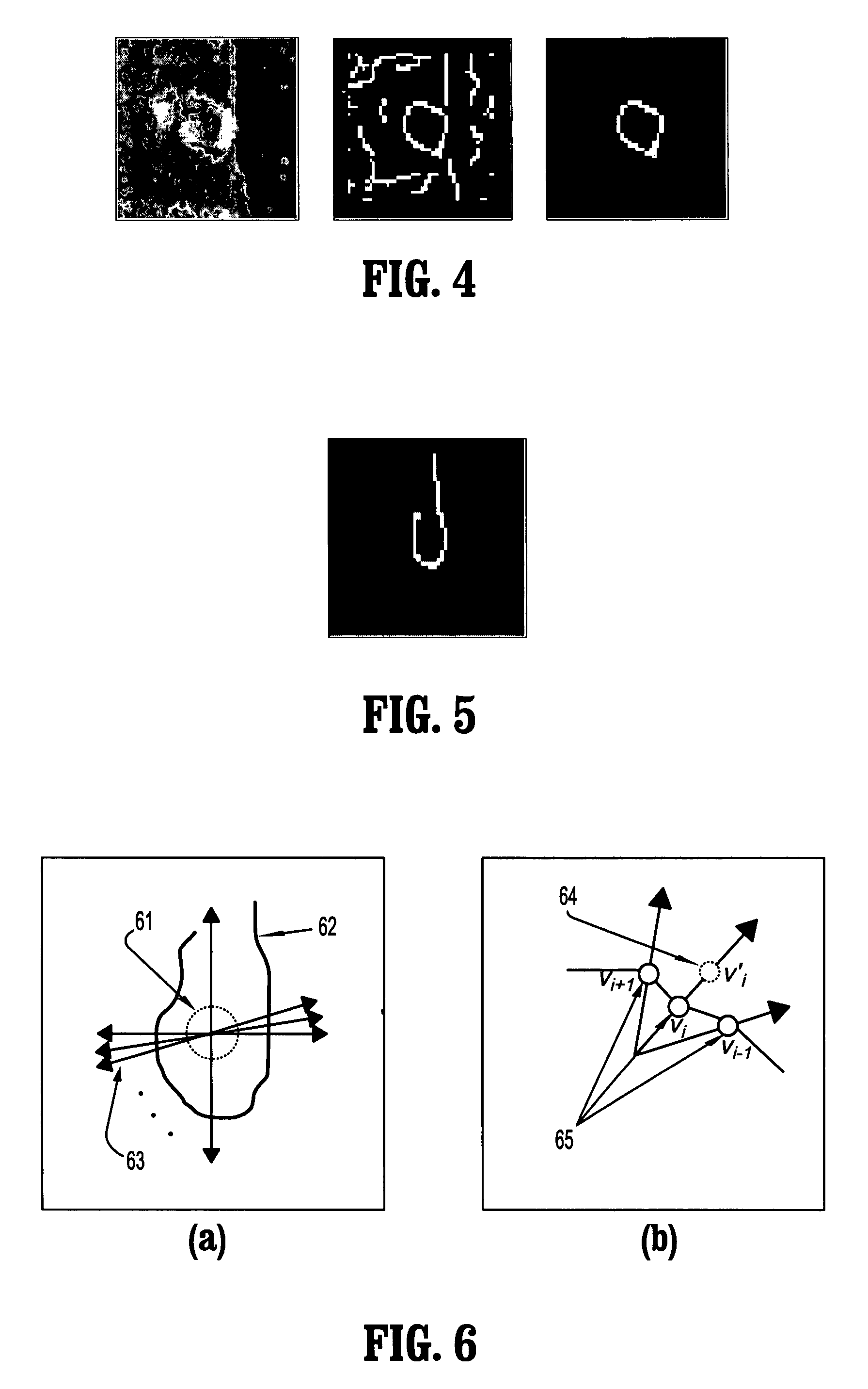
[0015]According to a further aspect of the invention, deforming a closed curve comprises minimizing an energy function of a plurality of points representing said closed curve, wherein said minimization is constrained by said ridge points.
[0016]According to a further aspect of the invention, the energy function comprises a first term that is a function of the distance between a point on said closed curve and a corresponding ridge point, a second term representing a force that causes the closed curve to expand outward, and a third term that causes the curve to contract if a curve point has advanced beyond the ridge points, and helps the curve expand if a curve point is within the ridge points.

Problems solved by technology

The advances in medical imaging equipment have brought efficiency and high capability imaging modalities, such as multi-slice CT scanners, produce large amount of digital data that is difficult and tedious to be interpreted merely by physicians.
It is challenging to obtain good results from rib segmentation.
Tracing rib posteriors is challenging due to the fact that ribs and vertebrae are so close at the posterior junctions that the gaps between them are vague and hard to locate.
Edge detectors have difficulty locating rib edges in the posterior section and the results are usually inaccurate.
This is because the junction area (where rib and vertebrae are very close or connected) contains a mixture of lines, edges and other contour-like structures, and a linear edge detector cannot respond appropriately to the various contour structures.
Since the 1970s, many methods to detect and label ribs automatically in 2D chest radiographs have been developed, but there has been little work in 3D extraction of individual rib structures.
Although the intensity of rib bone is much higher than the surrounding tissues, these region growing methods fail to provide satisfactory results.
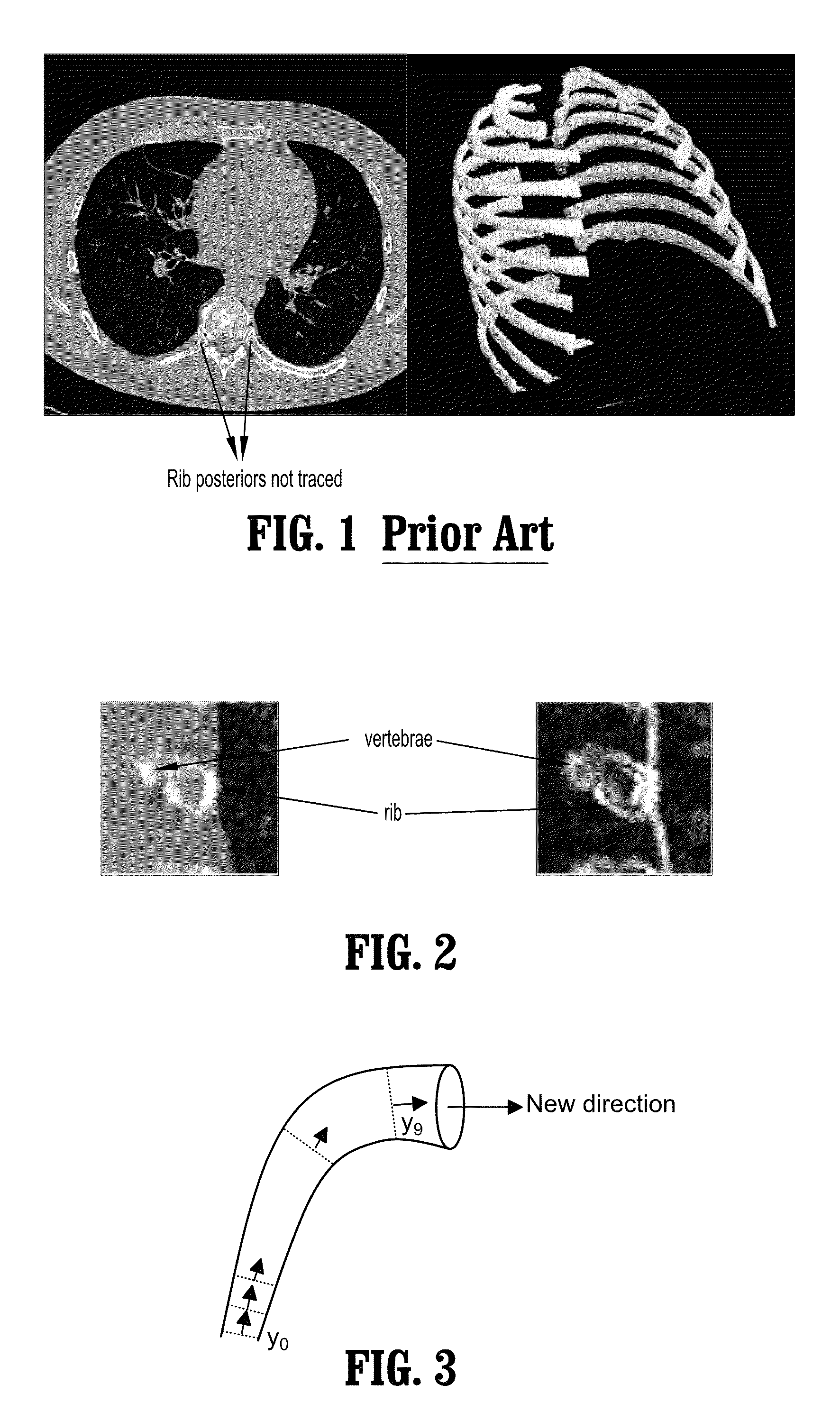
However, as shown in FIG. 1 by the arrows pointing to untraced rib posteriors, each tracing routine stops at a certain point in the posterior section, due to a lack of accurate detected rib edge points, and therefore the energy term used as a criterion for verifying a correct tracing path is no longer valid.

Method used


Image

  • System and method for tracing rib posterior in chest CT volumes
  • System and method for tracing rib posterior in chest CT volumes
  • System and method for tracing rib posterior in chest CT volumes

Examples


Embodiment Construction

[0032]Exemplary embodiments of the invention as described herein generally include systems and methods for tracing rib posteriors using a ridge based approach, starting from the segmentation result from the method of Shen, et al. Accordingly, while the invention is susceptible to various modifications and alternative forms, specific embodiments thereof are shown by way of example in the drawings and will herein be described in detail. It should be understood, however, that there is no intent to limit the invention to the particular forms disclosed, but on the contrary, the invention is to cover all modifications, equivalents, and alternatives falling within the spirit and scope of the invention.

[0033]As used herein, the term “image” refers to multi-dimensional data composed of discrete image elements (e.g., pixels for 2-D images and voxels for 3-D images). The image may be, for example, a medical image of a subject collected by computer tomography, magnetic resonance imaging, ultras...


PUM


Abstract

A method for tracing, rib posteriors includes providing an incomplete rib tracing comprising a digitized 3-dimensional representation of a rib and a digital image from which said rib tracing was extracted, initializing, a tracing direction for a remainder of said rib, detecting a plurality of ridge points in a sub-volume of said digital image about said initial tracing direction, and deforming a closed curve in a plane perpendicular to said tracing direction until a rib-edge contour is obtained, using said ridge points as constraints.

Description

CROSS REFERENCE TO RELATED UNITED STATES APPLICATIONS[0001]This application claims priority from: “A Robust Method of Tracing Rib Posterior in Chest CT Volumes”, U.S. Provisional Application No. 60 / 728,068 of Qing, et al., filed Oct. 19, 2005, the contents of which are incorporated herein by reference.TECHNICAL FIELD[0002]This invention is directed to 3D visualization of rib structures in medical computer-aided diagnosis (CAD) systems.DISCUSSION OF THE RELATED ART[0003]The advances in medical imaging equipment have brought efficiency and high capability imaging modalities, such as multi-slice CT scanners, produce large amount of digital data that is difficult and tedious to be interpreted merely by physicians. Computer Aided Diagnosis (CAD) systems will therefore play a critical role, especially in the visualization, segmentation, detection, registration, and reporting of medical pathologies. Due to the large volume of the data involved and the on-time requirement of medical applica...

Claims


Application Information

Patent Timeline
Patent Type & Authority Patents(United States)
IPC IPC(8): G06K9/00
CPCG06T7/0091G06T7/0012G06T7/155
Inventor QING, SHUPINGSHEN, HONG
Owner SIEMENS MEDICAL SOLUTIONS USA INC
Learn More