
Power tools
a technology for power tools and rip guides, which is applied in the field of power tools, can solve the problems of non-standard attachment interfaces of portable tool spindles, preventing the attachment of standard cutting elements, etc., and achieves the effects of improving the durability of the rip guide, and quick and easy removal of perforated materials
- Summary
- Abstract
- Description
- Claims
- Application Information
AI Technical Summary
Benefits of technology
Problems solved by technology
Method used
Image

Examples
Embodiment Construction
[0019]The following description is merely exemplary in nature and is not intended to limit the present disclosure, application, or uses. It should be understood that throughout the drawings, corresponding reference numerals indicate like or corresponding parts and features.
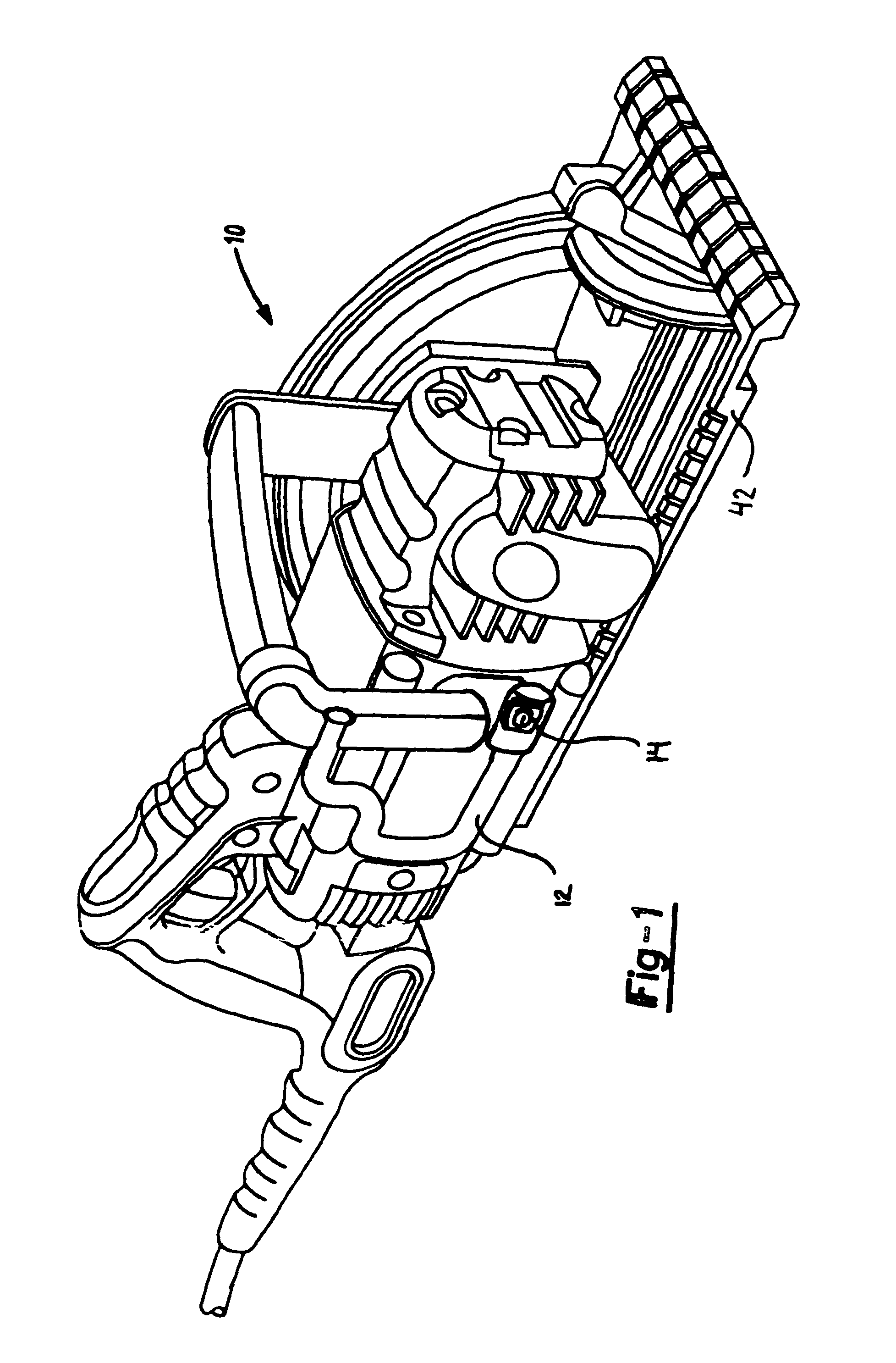
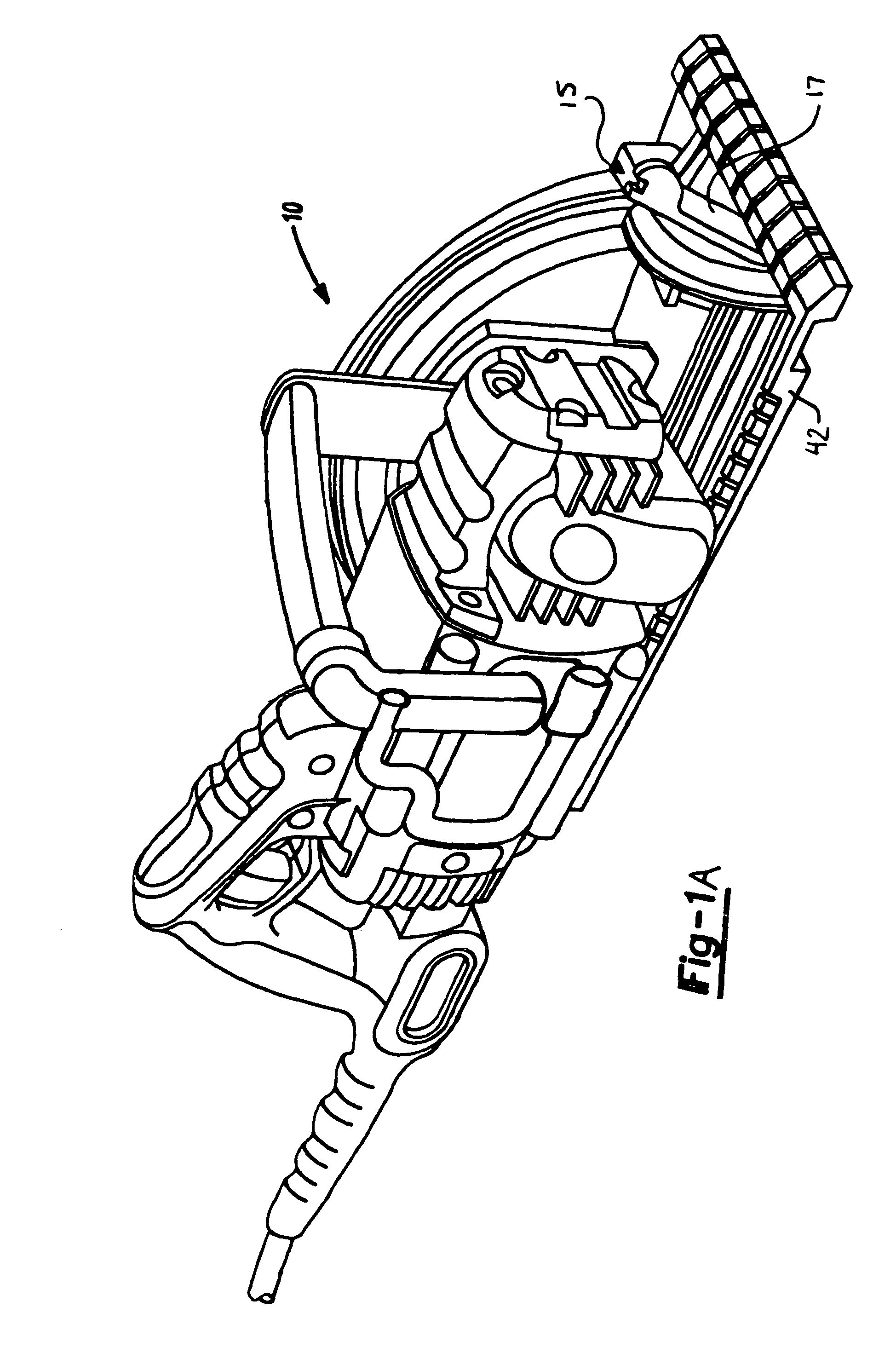
[0020]With reference to FIG. 1, an exemplary power tool 10 is shown including a hanger 12 pivotally attached to the tool to allow the hanger 12 to be moved between a use position and a non-use position. As illustrated in FIG. 1, attached to the hanger 12 is a perforated material remover 14. Although shown attached to the hanger 12, the perforated material remover 14 can be attached to any portion of the power tool 10. For example, FIG. 1A shows an alternative embodiment of a perforated material remover 15 attached to a bevel lever 17.
[0021]Turning to FIG. 2, the perforated material remover 14 can be seen more clearly. In a preferred embodiment, the perforated material remover 14 includes a body portion 16 which is...
PUM
| Property | Measurement | Unit |
|---|---|---|
| length | aaaaa | aaaaa |
| durability | aaaaa | aaaaa |
| size | aaaaa | aaaaa |
Abstract
Description
Claims
Application Information