
Pressure sensor for measurements in hot, dynamic processes

a technology of pressure sensor and hot process, applied in the direction of fluid pressure measurement by mechanical elements, measuring devices, instruments, etc., can solve the problems of inevitability of thermal deformation of sensor components, expansion of support, and distorted radial force, and achieve the effect of large radial for

Inactive Publication Date: 2011-05-31
KISTLER HLDG AG
View PDF13 Cites 5 Cited by
  • Summary
  • Abstract
  • Description
  • Claims
  • Application Information

AI Technical Summary

Benefits of technology

The present invention is about a pressure sensor that is insensitive to temporary temperature peaks. The invention achieves this by using a heat shield on the housing projection, which reduces heating of the sensor tip and minimizes distortion and tension of the membrane, resulting in less measurement error. The invention also avoids deformation of the sensor components to avoid measurement errors caused by impact. The heated membrane generates large radial forces, which are restrained by the supports and do not impact the measuring element. The invention also avoids distortion of the supports, ensuring accurate alignment of the membrane.

Problems solved by technology

The thermal deformations of the sensor components are inevitable.
On the other hand the support itself is heated and is distorted by its expansion.

Method used


Image

  • Pressure sensor for measurements in hot, dynamic processes
  • Pressure sensor for measurements in hot, dynamic processes

Examples


Embodiment Construction

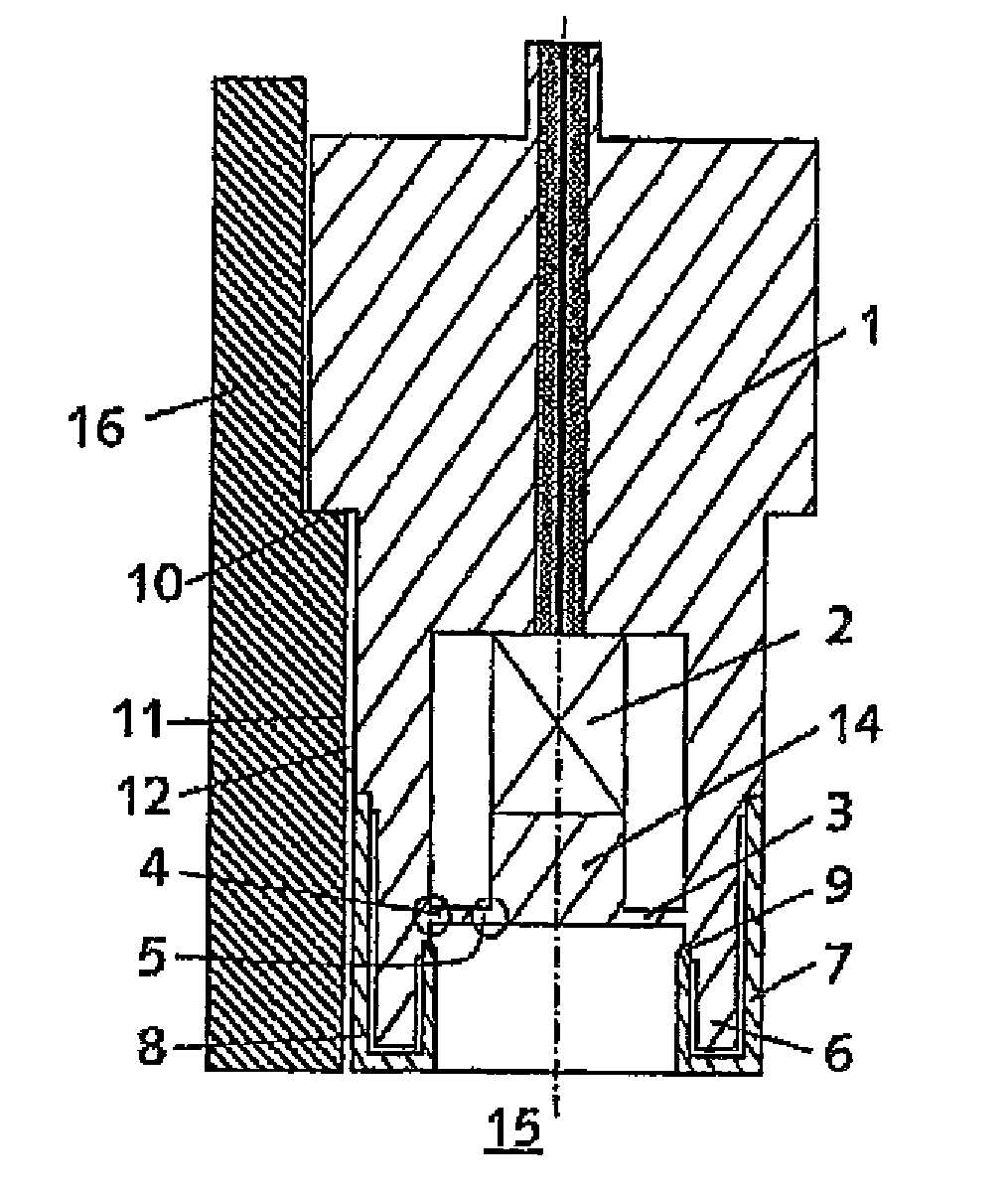
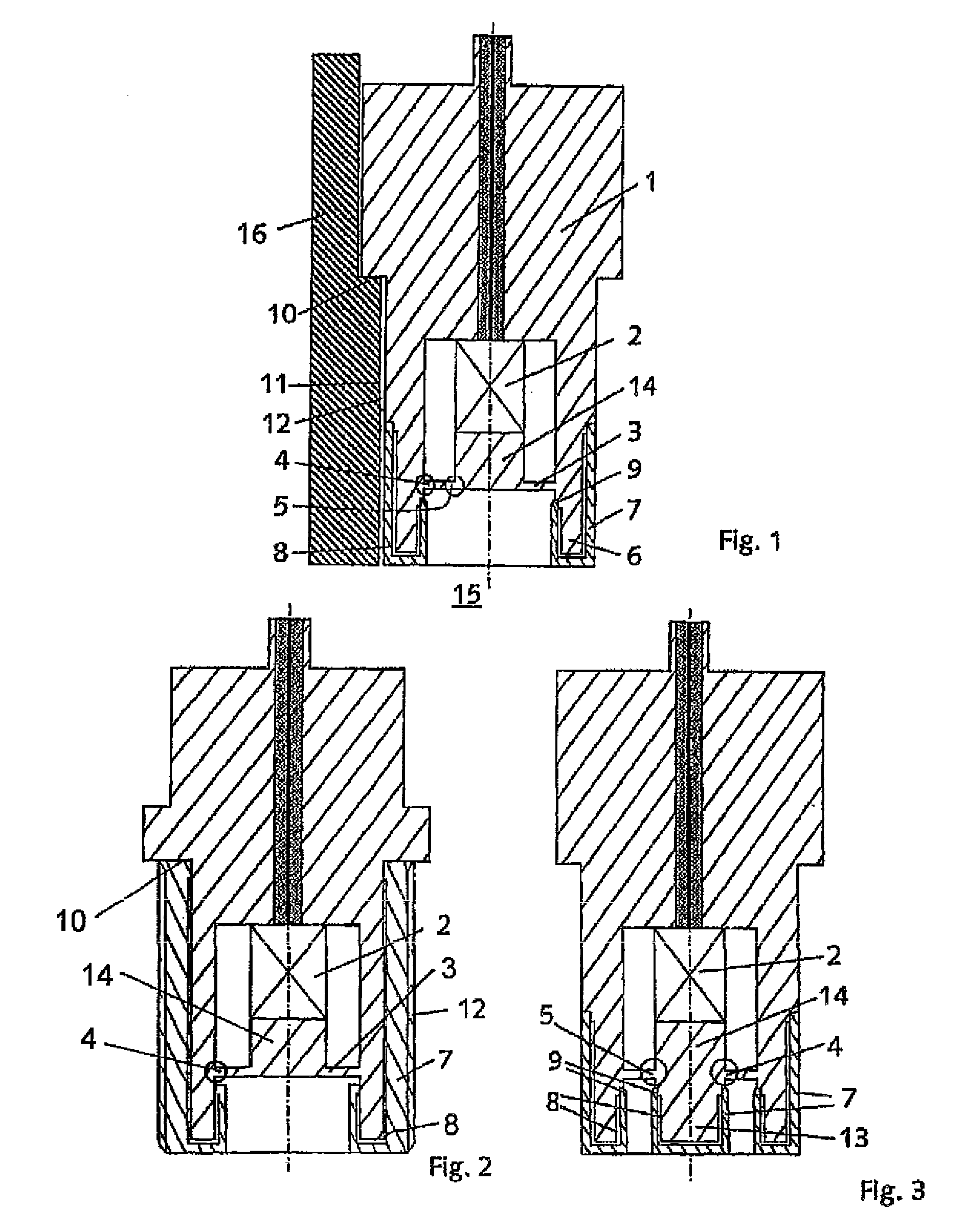
[0014]FIG. 1 shows a representation of a pressure sensor according to the invention for the measurement in hot, dynamic processes in cross-section built into a device 16 on one side. In front of the sensor there is for example a combustion chamber 15, the pressures of which are to be measured by the sensor.

[0015]The sensor comprises a housing 1 in which a measuring element 2 is disposed as well as a round membrane 3 having an outer support 4. This support 4 can be considered as a hinge around which the membrane 3 can pivot. The measuring element can capture measurement data due to an axial displacement of the membrane 3. Therefore, axial displacements which do not result from a pressure differential in the combustion chamber 15 but from thermal expansion of sensor components produce an erroneous measurement. However, radial expansions of the membrane 3 do not cause a measurement error.

[0016]The support 4 on the housing 1 is arranged in an offset manner behind a housing extension 6. ...


PUM

PropertyMeasurementUnit
temperatureaaaaaaaaaa
temperaturesaaaaaaaaaa
axial displacementaaaaaaaaaa

Abstract

The invention relates to a pressure sensor for measurements in hot, dynamic processes. The pressure sensor comprises a cylindrical housing in which a measuring element is located, and a round or annular membrane having at least one outer support. The outer support is arranged on the housing, offset behind a housing extension. The measuring element is adapted to acquire measurement data as a result of an axial displacement of the membrane. The housing extension is provided with a heat shield which is arranged, except on its edges, interspaced behind a gap.

Description

CROSS-REFERENCE TO RELATED APPLICATIONS[0001]This application claims priority to International Application Ser. No. PCT / CH2007 / 000557 filed Nov. 12, 2007, which claims priority to Austrian Application No. A 1866 / 2006 filed Nov. 10, 2006.TECHNICAL FIELD[0002]The invention relates to a pressure sensor for measurement in hot, dynamic processes comprising a cylindrical housing in which a measuring element is located as well as a round or annular membrane having at least one outer support wherein the outer support is arranged on the housing offset behind a housing extension, according to the characterizing part of the first claim.BACKGROUND[0003]Measurement in hot, dynamic processes is often subject to measurement errors originating from thermally induced deformations of the sensor front. Since the measuring elements within the sensors detect measurement data due to an axial displacement of the membrane, erroneous measurements result from tilting of the membrane clamping.[0004]Ignitions ...

Claims


Application Information

Patent Timeline
Patent Type & Authority Patents(United States)
IPC IPC(8): G01L7/00
CPCG01L19/04G01L23/28G01L23/10
Inventor GLASER, JOSEF
Owner KISTLER HLDG AG
Learn More