
System and method for thru tubing deepening of gas lift

a technology of gas lift and gas tubing, which is applied in the direction of fluid removal, earthwork drilling and mining, borehole/well accessories, etc., can solve the problems of limiting and reducing the effectiveness of gas lift. achieve the effect of preventing blowou

Active Publication Date: 2011-06-07
BAKER HUGHES INC
View PDF41 Cites 3 Cited by
  • Summary
  • Abstract
  • Description
  • Claims
  • Application Information

AI Technical Summary

Benefits of technology

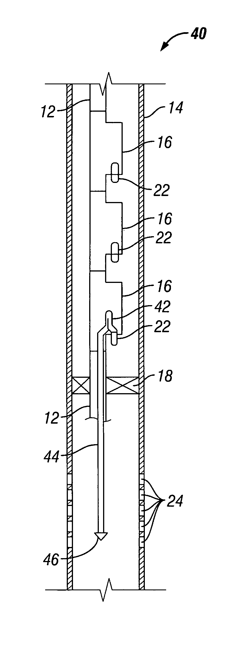
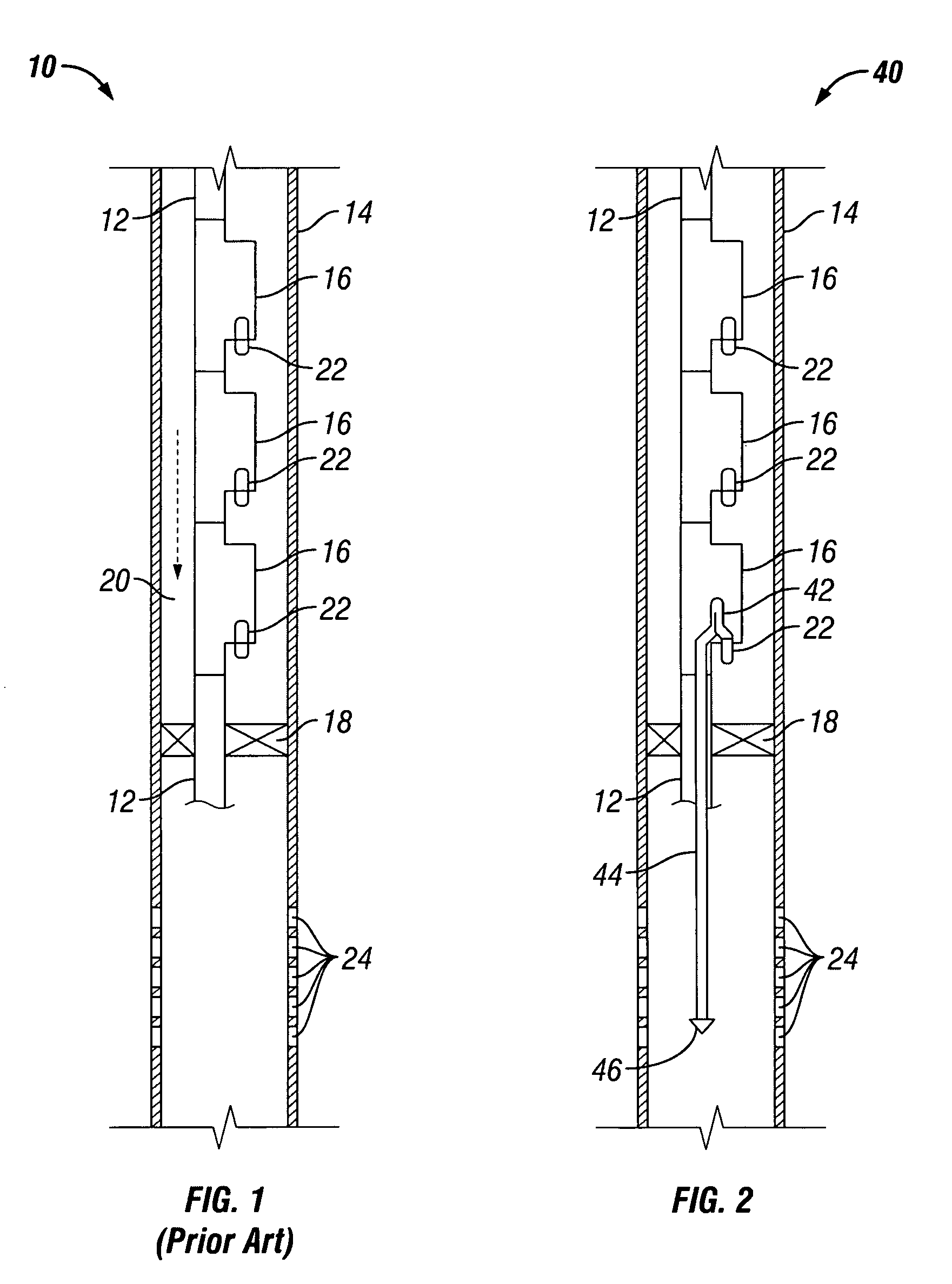
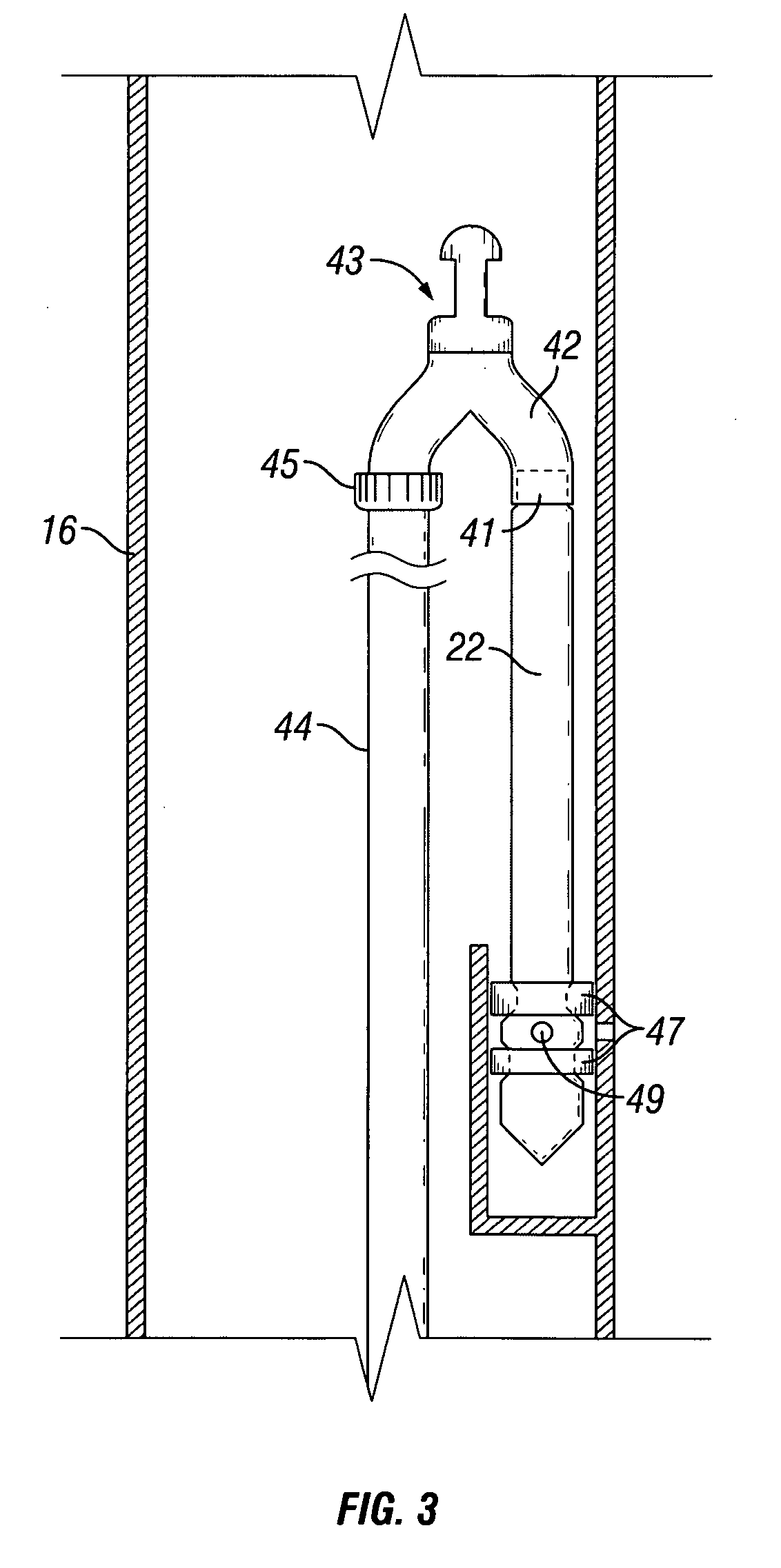
The present patent is about a gas lift system that can be used to inject gas into a wellbore at a deeper location. The system includes a turn-over suspension mandrel that is connected to a gas lift valve and a coil. The system also includes a production tubing with a production packer to seal the annulus between the tubing and the well casing. The gas lift valve directs gas into the wellbore through the coil and to a deeper location beneath the production packer. A plug can be placed at the bottom of the coil to prevent blowouts during installation of the gas lift system. Another embodiment of the patent provides a coil and plug hung from the gas lift valve of a pack-off assembly. The technical effect of this patent is to provide a reliable and safe method for injecting gas into a wellbore at a deeper location.

Problems solved by technology

There are drawbacks to the current gas lift systems.
On occasion, depletion of the well causes the gas lift to become less effective.
However, even after the workover is completed, the deepest depth of the lowest gas injection point will be only slightly above the production packer, limiting the effectiveness of the gas lift.

Method used


Image

  • System and method for thru tubing deepening of gas lift
  • System and method for thru tubing deepening of gas lift
  • System and method for thru tubing deepening of gas lift

Examples


Embodiment Construction

[0013]Illustrative embodiments of the disclosure are described below as they might be employed in the construction and use of a gas lift system and method according to the present disclosure. In the interest of clarity, not all features of an actual implementation are described in this specification. It will of course be appreciated that in the development of any such actual embodiment, numerous implementation-specific decisions must be made to achieve the developers' specific goals, such as compliance with system-related and business-related constraints, which will vary from one implementation to another. Moreover, it will be appreciated that such a development effort might be complex and time-consuming, but would nevertheless be a routine undertaking for those of ordinary skill in the art having the benefit of this disclosure.

[0014]Further aspects and advantages of the various embodiments and methods of the present disclosure will become apparent from consideration of the followin...


PUM


Abstract

The present disclosure is directed to a gas lift system adapted to provide a gas injection point to a deeper location in a wellbore. A turn-over suspension mandrel can be landed inside a side pocket mandrel and connected to a gas lift valve on one end and a coil on the other end. A length of production tubing can extend from the side pocket mandrel. The production tubing can include a production packer to seal the annulus between the tubing and the well casing. The turn-over suspension mandrel can be constructed such that gas entering the gas lift valve is directed down through the coil and into the wellbore beneath the production packer. A plug can be placed at the bottom of the coil in order to prevent blowouts during installation of the gas lift system. An alternative embodiment of the present disclosure provides a coil and plug hung from a gas lift valve of a pack-off assembly.

Description

BACKGROUND[0001]1. Field of the Disclosure[0002]The present disclosure relates, in general, to gas lift systems and, in particular, to a gas lift system adapted to introduce gas to a deeper location in the wellbore.[0003]2. Description of the Related Art[0004]Gas lift systems are typically designed and installed as part of a downhole completion in an oil well. The purpose of a gas lift system is to introduce gas below the fluid column in order to increase the velocity of the fluid, thereby lifting the fluid to the surface. Gas lift systems typically have several locations or injection points, from top to bottom, for the release of gas within the wellbore. Due to the nature of packers and sand screens used in wells today, the gas injection points are located above the packer and / or screen. The most important of these injection points is generally the lowest injection point in the well.[0005]There are drawbacks to the current gas lift systems. On occasion, depletion of the well causes...

Claims


Application Information

Patent Timeline
Patent Type & Authority Patents(United States)
IPC IPC(8): E21B43/00
CPCE21B43/122E21B34/105E21B43/123
Inventor BOLDING, JEFFREY L.
Owner BAKER HUGHES INC
Learn More