
Image forming apparatus, image forming system, and control program thereof to manage printing sheet communications

a technology of image forming apparatus and control program, which is applied in the direction of digital output to print units, instruments, digitally marking record carriers, etc., can solve the problems of large number of types of sheets to be stored, complicated control operation, and many times of poorly fixed toner

Inactive Publication Date: 2011-06-07
CANON KK
View PDF13 Cites 218 Cited by
  • Summary
  • Abstract
  • Description
  • Claims
  • Application Information

AI Technical Summary

Benefits of technology

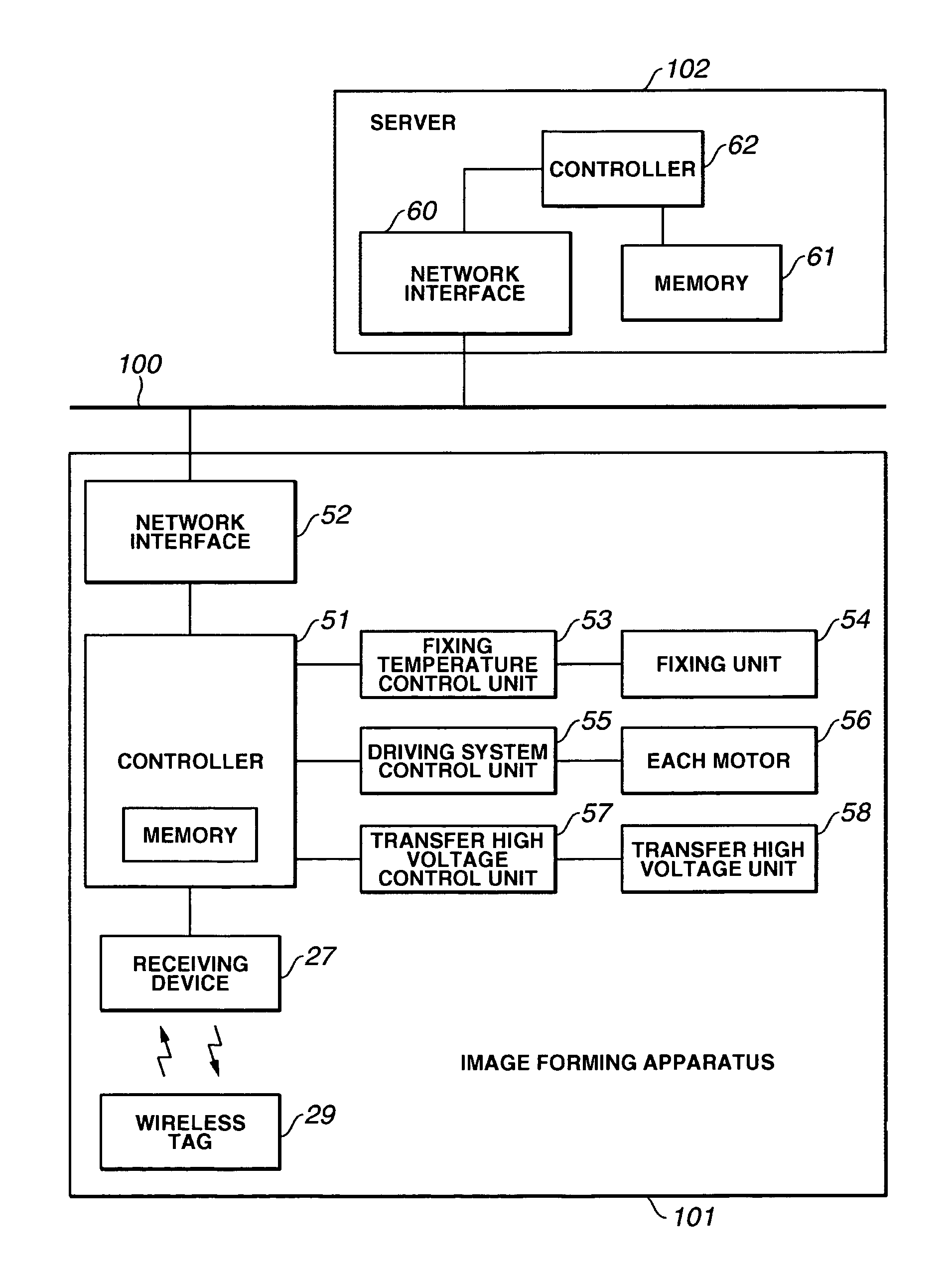
The present invention is about an image forming system that can detect the type of sheet used and adjust the image forming settings accordingly without needing sensors. The system includes an image forming apparatus and a server that manages control information for the apparatus. The apparatus has a sheet storing device that stores sheets with wireless tags, a receiving device that receives information from the wireless tags, and a communication device that obtains control information from the server via a network. The control information is then sent to a controller in the apparatus to control the image forming conditions. This allows for optimal image forming control based on the type of sheet used.

Problems solved by technology

Thus, with color image which uses a larger amount of toner than in the case of a monochromatic image, the toner many times is poorly fixed because the toner is not sufficiently melted.
Thus, the number of sensors becomes too large, resulting in complicating a control operation.
In addition, in the case where information related to various kinds of sheets and control information are previously stored in an image forming apparatus, the number of types of sheets to be stored becomes significantly large.
Further, in the case of a sheet whose information is not previously stored, an optimum control operation cannot be performed.

Method used


Image

  • Image forming apparatus, image forming system, and control program thereof to manage printing sheet communications
  • Image forming apparatus, image forming system, and control program thereof to manage printing sheet communications
  • Image forming apparatus, image forming system, and control program thereof to manage printing sheet communications

Examples


first exemplary embodiment

[0041]A first exemplary embodiment of an image forming system according to the present invention is described with reference to the drawings.

[0042]Here, in the explanation as to the embodiments of the present invention, an image forming apparatus includes apparatuses such as a copying machine, a laser beam printer, a facsimile machine, and a multifunction machine having a copying function, a printer function, a facsimile function, and the like. In addition, in the description of the embodiments below, an explanation is made as to a color image forming apparatus as an example. However, the present invention can also be applied to a monochromatic image forming apparatus.

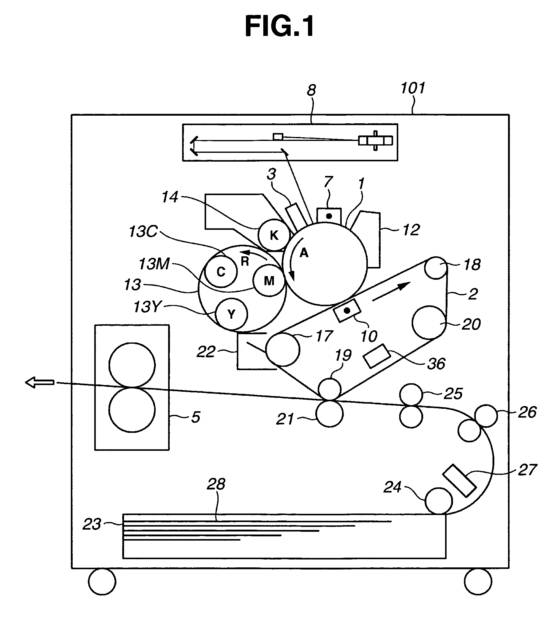
[0043]FIGS. 1 through 7 show an exemplary image forming system according to the first embodiment of the present invention.

[0044]First, FIG. 1 is a cross section of an exemplary printer unit of the image forming apparatus. More specifically, FIG. 1 shows an exemplary color image forming apparatus having an intermediate ...

second exemplary embodiment

[0084]A second exemplary embodiment of an image forming system according to the present invention is explained with reference to the drawings.

[0085]FIGS. 8 and 9 are cross sections showing a printer unit of the image forming apparatus according to the image forming system that is the second embodiment of the present invention. Note that a basic constitution of the second embodiment is similar the constitution of the first embodiment, and accordingly, the portions having the same constitution are provided with the same reference numerals and symbols, and the explanation thereof is not repeated here.

[0086]FIG. 8 shows an embodiment in which a plurality of sheet cassettes are provided and a same number of receiving devices are also provided. In FIG. 8, the printer unit is provided with two sheet cassettes, namely, a sheet cassette 23 and a sheet cassette 33. Reference numeral 30 denotes a pickup roller for the sheet cassette 33, and reference numeral 31 denotes a receiving device for t...

third exemplary embodiment

[0095]The pickup roller 24 mentioned above may be comprised by two rollers of a semi-circular shape whose one part is cut off, as shown in FIG. 10. In the sheet cassette 23, a bundle of the sheet 28 is lifted from a bottom of a feeding side (namely, the side an arrow A in FIG. 10 indicates) of a sheet 28 that is positioned at the bottom of the bundle of the sheet 28. Thus, the pickup roller 24 separates one sheet that is positioned at the top of the bundle of the sheet 28 stacked in the sheet cassette 23, and conveys the separated sheet 28 to the conveyance path.

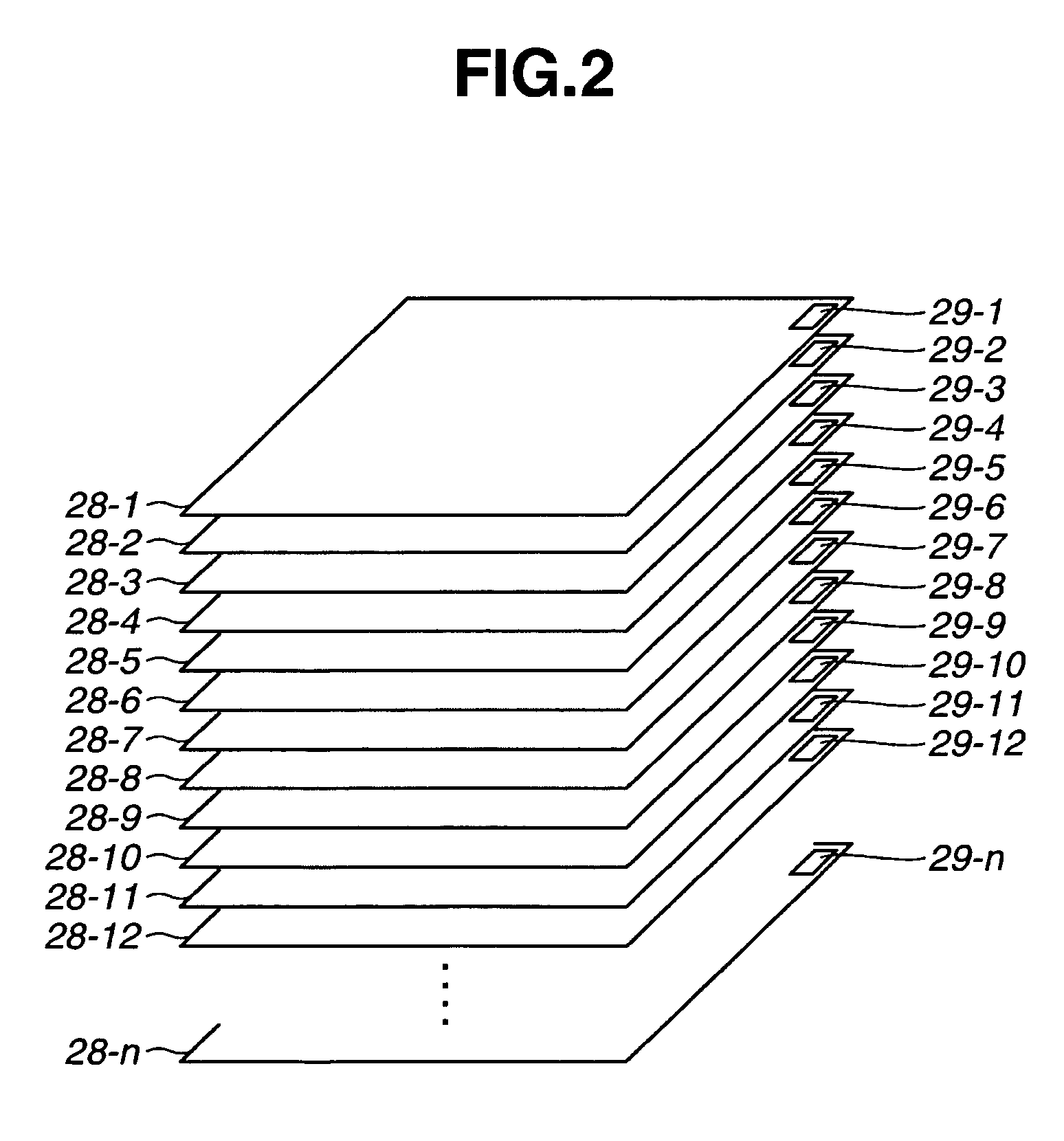
[0096]Here, with respect to a relationship between the thickness of the sheet 28 and the wireless tag 29, there is a case, for example, where a thickness t1 of the sheet 28 is smaller than a thickness t2 of the wireless tag 29, as shown in an upper part of FIG. 11. In addition, as shown in a lower part of FIG. 11, there is a case where the wireless tag 29 is mounted inside the sheet by holding the wireless tag 29 between she...


PUM


Abstract

An image forming apparatus is provided, in carrying out an image forming operation using a paper sheet, that uses a sheet containing a wireless tag that stores an address storing control information for performing an optimum image forming. The image forming apparatus obtains the address from the wireless tag using a receiving device, and obtains control information from a server via a network based on the obtained address. The image forming apparatus controls an image forming condition based on the control information, and carries out the image forming under image forming conditions optimum for the sheet.

Description

BACKGROUND OF THE INVENTION[0001]1. Field of the Invention[0002]The present invention relates to an image forming apparatus that can be connected to a network, an image forming system including the image forming apparatus, and a control program thereof.[0003]2. Description of the Related Art[0004]In a conventional electro-photographic image forming apparatus such as a copying machine or a laser beam printer, the thickness of a sheet is so significant, in forming an image on the sheet, that the thickness of the sheet determines a quality of the image. This is especially the case in a conventional color copying machine because the color copying machine forms one single image by superposing toners of four colors onto one single sheet. As a result, the amount of toner formed on a sheet is significantly larger than in the case of a monochromatic copying machine. Accordingly, in a color copying machine, a difference in the thickness of a sheet considerably affects the quality of an image....

Claims


Application Information

Patent Timeline
Patent Type & Authority Patents(United States)
IPC IPC(8): G06F15/00G06F3/12G06K1/00
CPCG03G15/5075B41J11/009
Inventor MINE, RYUTAYAMAUCHI, MANABUYAMADA, NAOTOIKEGAMI, HIDEYUKI
Owner CANON KK
Learn More