
Crown extrusion

a crown molding and extrusion technology, applied in the field of decorative moldings, can solve the problems of difficult application of crown molding, room corners, and exacerbated problems associated with crown molding installation

Inactive Publication Date: 2011-06-14
ROWOHLT TODD
View PDF31 Cites 25 Cited by
  • Summary
  • Abstract
  • Description
  • Claims
  • Application Information

AI Technical Summary

Benefits of technology

Facilitates easy installation of crown molding without specialized tools and allows for post-installation wiring options by providing a removable system that can be easily adjusted to fit various angles and surfaces, enhancing usability and flexibility.

Problems solved by technology

Generally speaking, crown molding is difficult to apply because it is applied at an angle defined by an inside edge on the backside of the crown molding and either the ceiling or the vertical wall.
Because wall and ceiling structures in most homes are uneven in that the surfaces of a vertical wall and ceiling do not create a 90-degree angle, the problems associated with installation of crown moldings are exacerbated.
Moreover, room corners, where two vertical walls meet a ceiling, require complex “compound miter” cuts requiring both a bevel cut and a miter cut, or difficult to apply coping cuts.
In order to carry out such cutting, a great deal of experience and expensive and complicated tools such as compound miter saws, coping saws, or air-driven or battery powered finish nailers are needed in order to effectively install the crown molding.
These conditions make the prospect of installing crown molding both daunting and expensive for an average homeowner requiring expertise that most “do-it-yourself” homeowners do not possess.
Because traditional crown molding is permanently mounted, opportunities for wiring in the space behind crown molding are generally limited to pre-installation wiring.

Method used


Image

  • Crown extrusion
  • Crown extrusion
  • Crown extrusion

Examples


Embodiment Construction

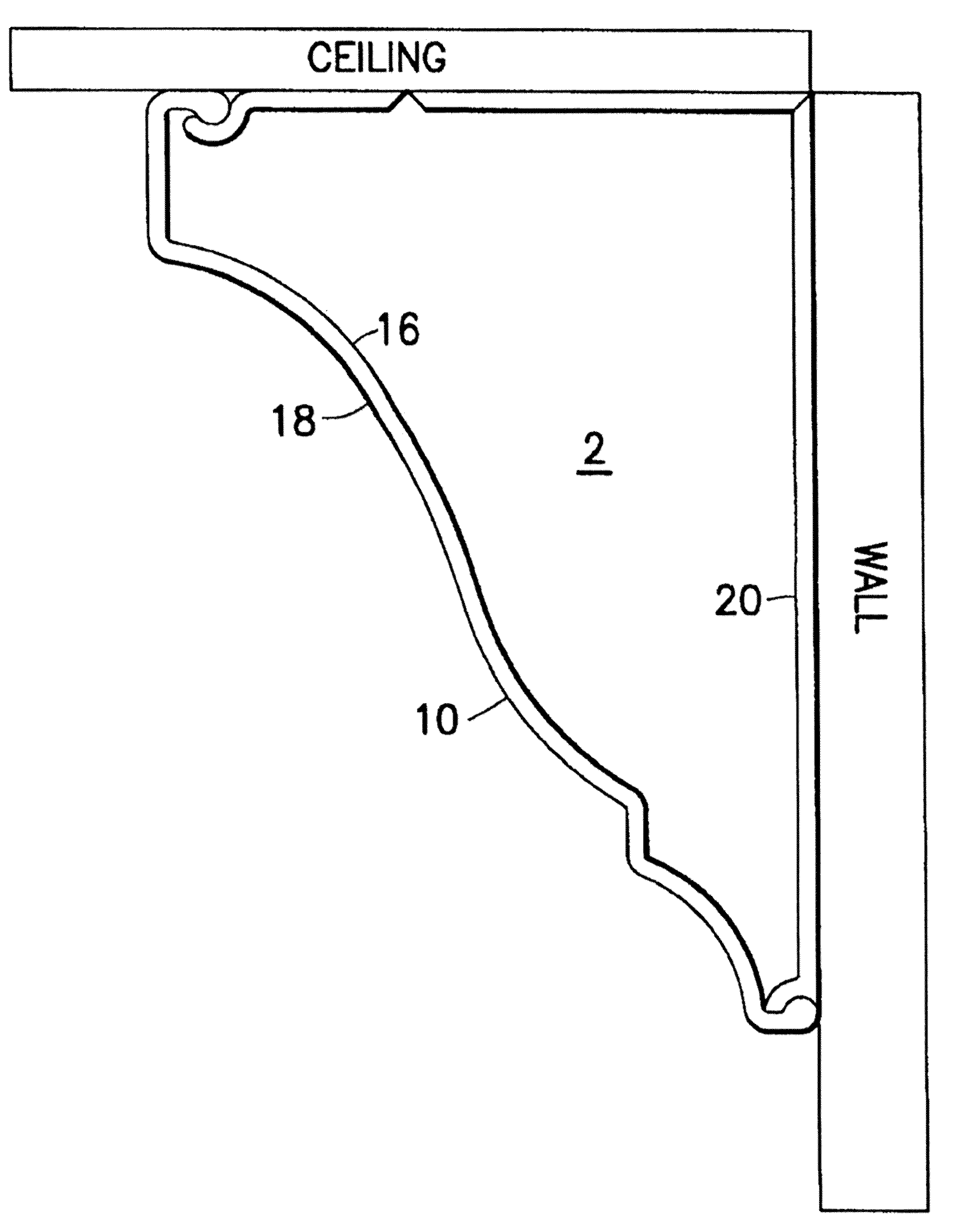
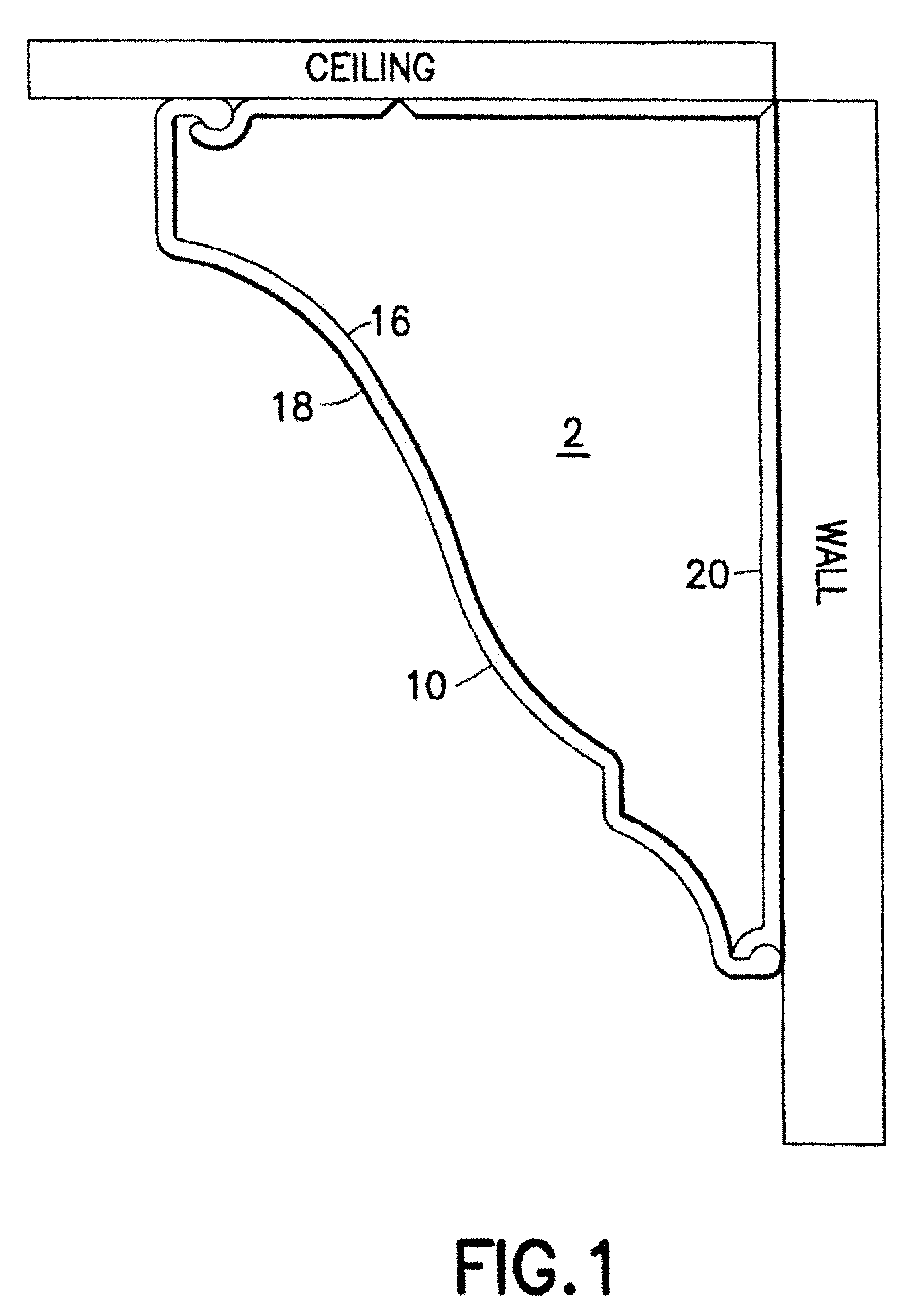
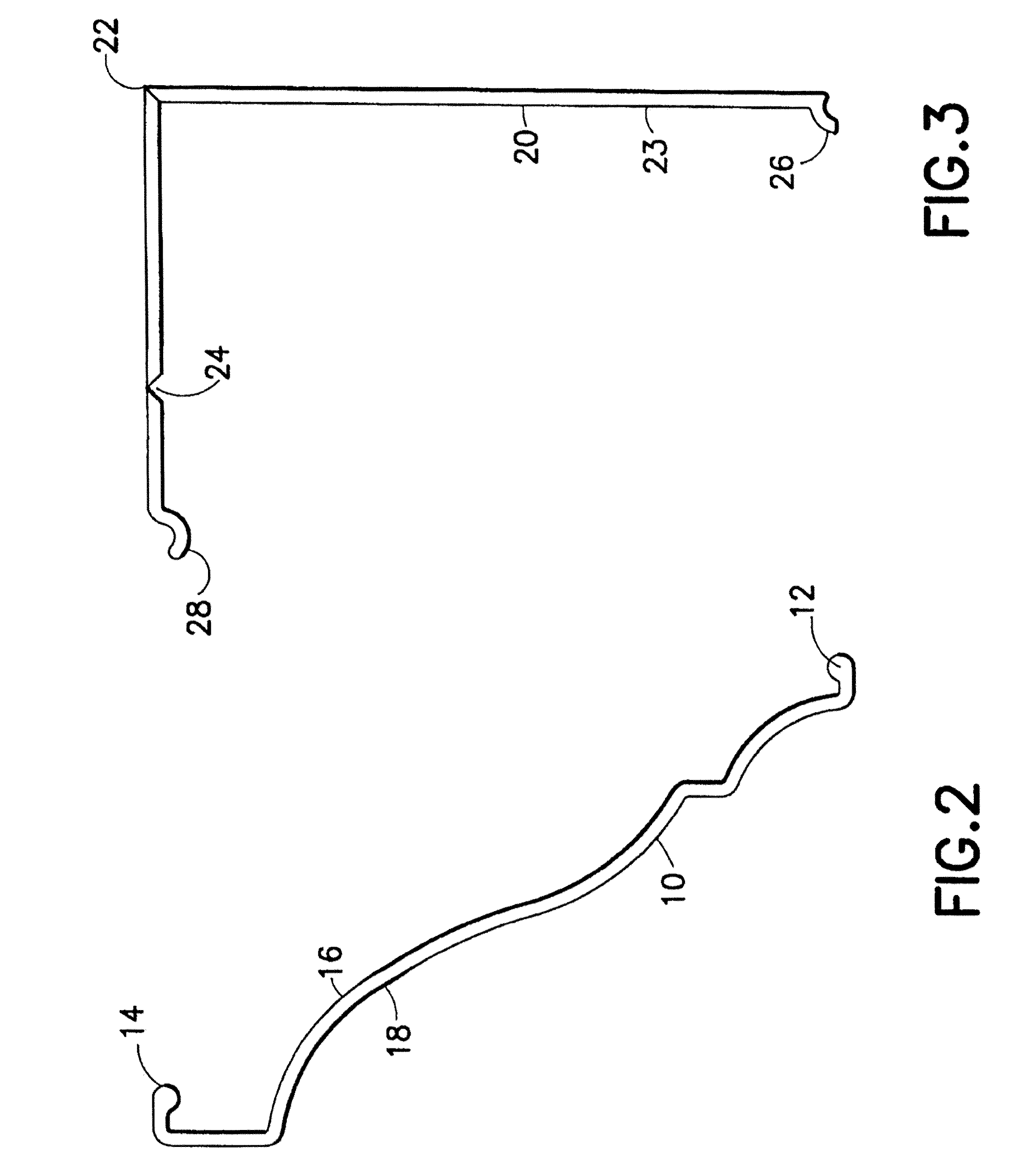
[0040]The present invention generally relates to a decorative molding system and a process of installing such a system, along with certain secondary decorative or functional items. In the following description, for purposes of explanation, specific numbers, materials and configurations are set forth in order to provide a thorough understanding of the invention. It will be apparent, however, to one having ordinary skill in the art that the invention may be practiced without these specific details. In some instances, well-known features may be omitted or simplified so as not to obscure the present invention.

[0041]Certain embodiments of the present invention will now be discussed with reference to the aforementioned figures, wherein like reference numerals refer to like components. It should be noted that reference in the specification to phrases such as “one embodiment” or “an embodiment” means that a particular feature, structure or characteristic described in connection with the emb...


PUM


Abstract

A decorative molding system and method of installation is provided that has a base piece and a crown piece that are adapted to be selectively engageable to each other. The molding system is easy to construct and allows for the separation of the base piece and crown piece for placing wiring or other materials behind the molding.

Description

CROSS-REFERENCE TO RELATED APPLICATION[0001]This application claims the benefit of now abandoned U.S. application Ser. No. 11 / 800,269, filed May 3, 2007, and U.S. Provisional Application Ser. No. 61 / 097,084, filed Sep. 15, 2008, entitled “Crown Extrusion,” the entire disclosure of each of which is hereby incorporated by reference.BACKGROUND OF THE INVENTION[0002]1. Field of the Invention[0003]The present invention relates to the field of decorative moldings and, in particular, to a selectively removable crown molding system.[0004]2. Description of Related Art[0005]Applying “crown molding” is the process by which a decorative molding is applied to the top edge of walls, cabinets, or other furniture. The process of applying crown molding is typically done along the seams where a ceiling meets a vertical wall. Generally speaking, crown molding is difficult to apply because it is applied at an angle defined by an inside edge on the backside of the crown molding and either the ceiling or...

Claims


Application Information

Patent Timeline
Patent Type & Authority Patents(United States)
IPC IPC(8): E04F19/04E04B2/00
CPCE04F19/0436H02G3/0425E04F19/0463E04F19/0495E04F2019/0413E04F2019/0454F21V33/0012F21V33/006E04F2019/044E04F2019/0427
Inventor ROWOHLT, TODD
Owner ROWOHLT TODD
Learn More